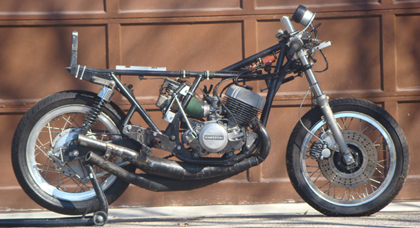
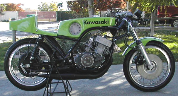
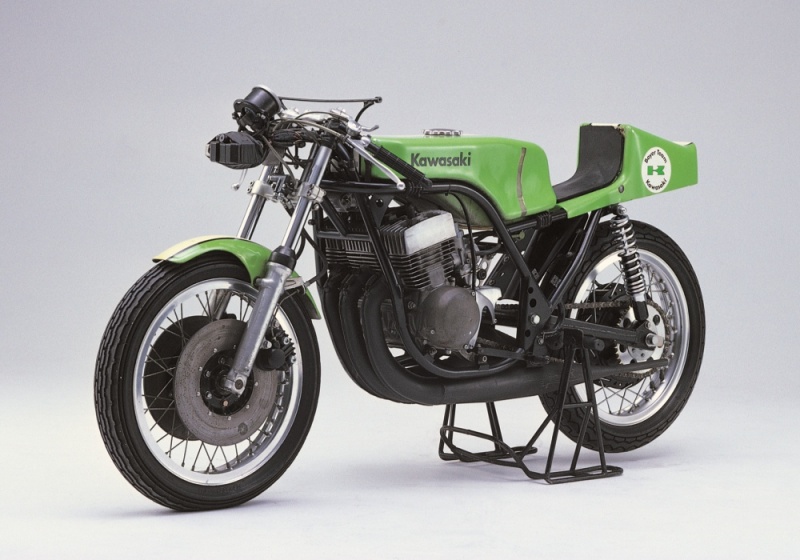
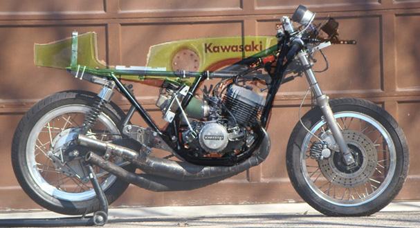
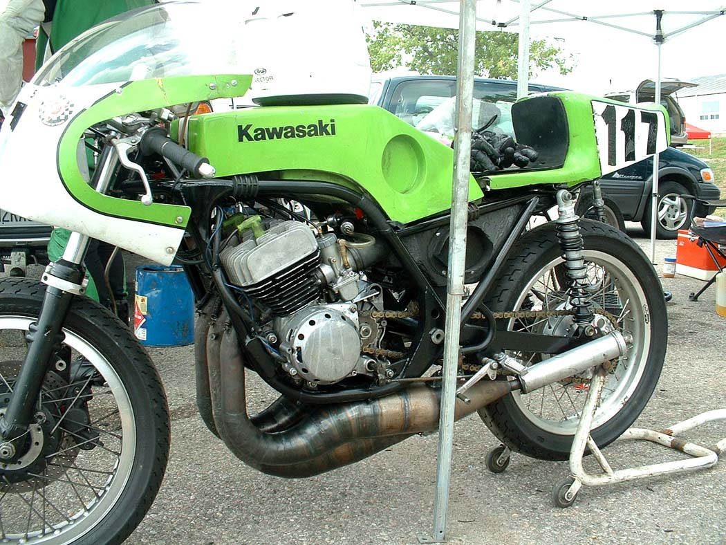
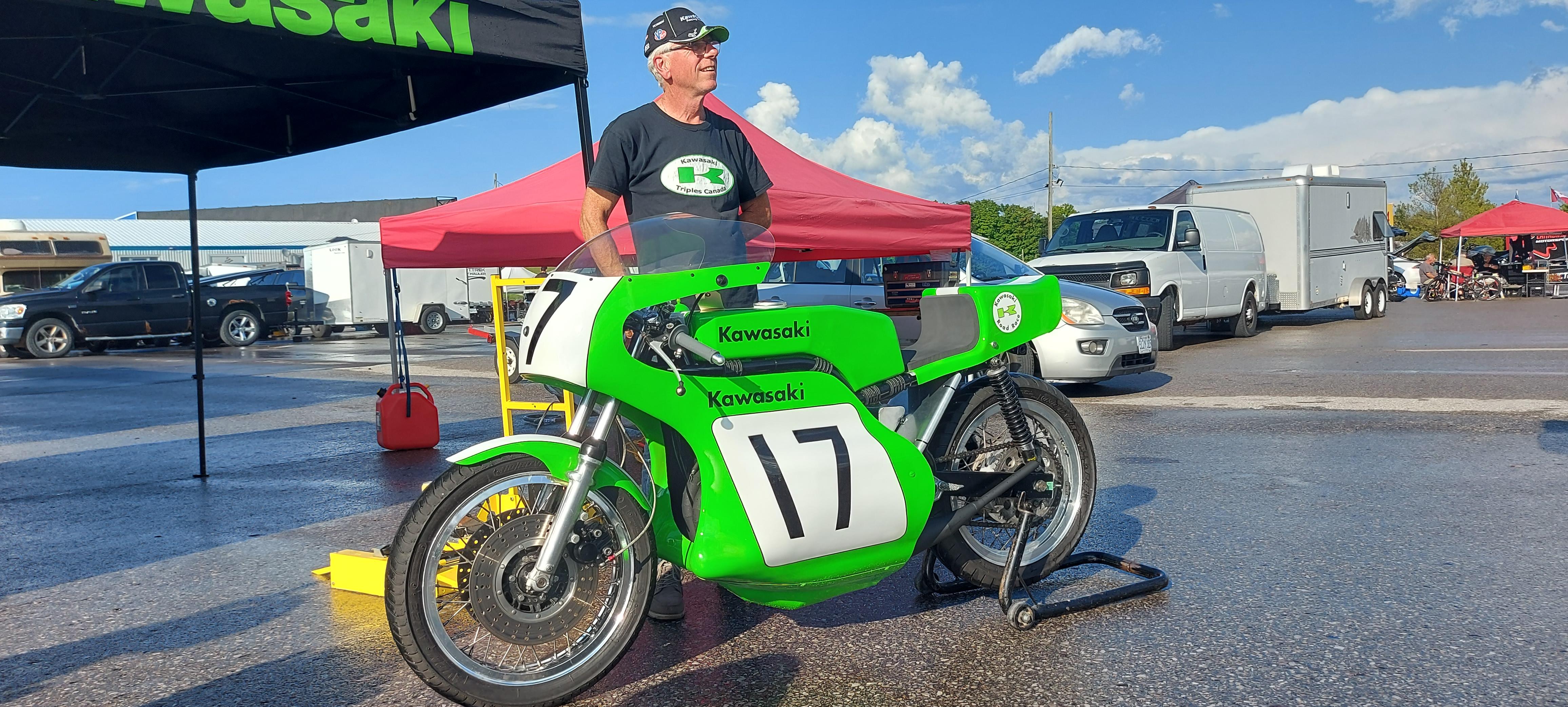
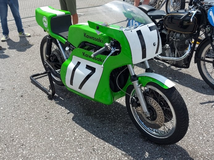
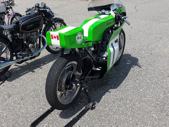
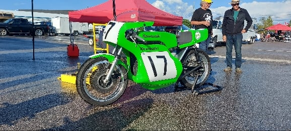
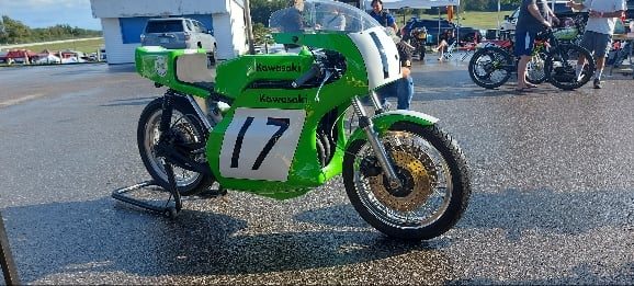
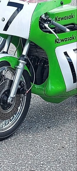
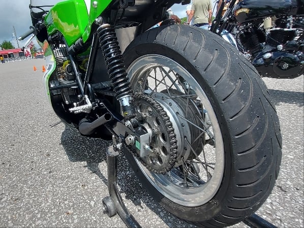
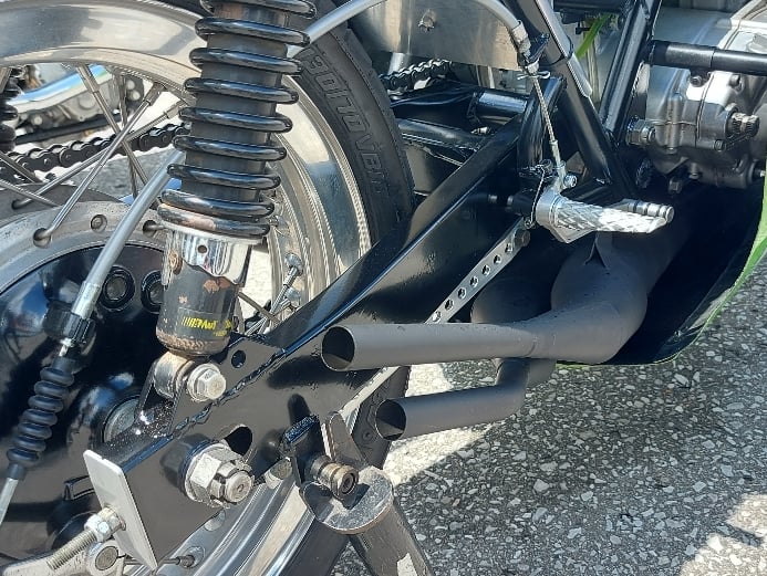
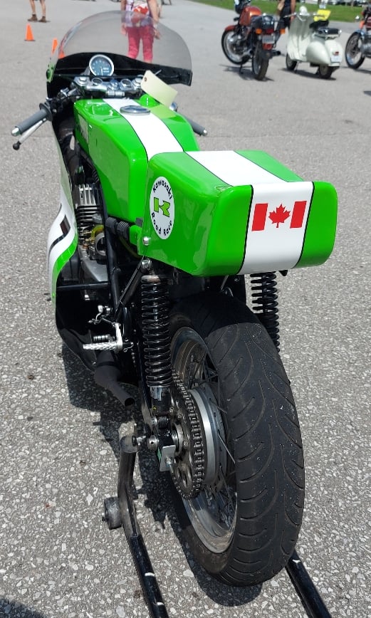
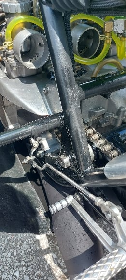
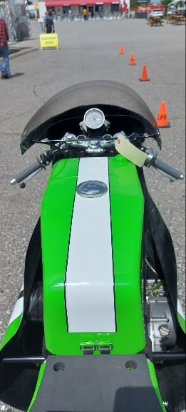
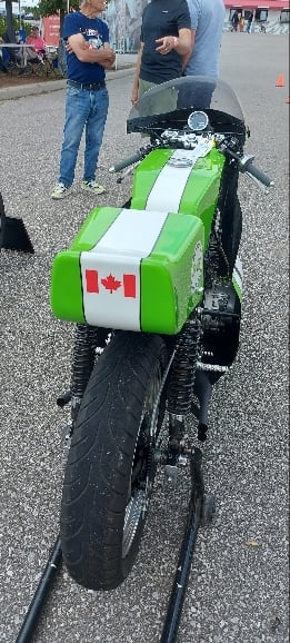
The build thread from the Kawasaki Triples Canada forum, where pipe welder built a look-alike of Kawasaki’s 1972 H2R road racer, starting from an H2R fairing and an H2C race bike. Saved here in November 2026: all 318 posts from November 2013 to June 2026, with replies from the rest of the forum.
164 of the 179 photos posted could still be found. The rest were stored on photo sites that have since deleted them, and are marked where they used to be. The original thread is at triplescanada.proboards.com.
Well as some of you know I started an H2r replica project some time ago and decided to finally start a Project Thread for this build.
I didn't want to post anything till I got in deep enough to decide if it was going to go ahead or die. Well it now looks like it's finally getting some where.
THE STORY:
Back around 2009 or 10 a friend call to to say there was an H2r fairing for sale on line and he knew I always talked about making a replica or "look alike" H2r. I called and went to see it and ended up with the fairing. Later I bought the H2C race bike that the owner of the fairing had and that gave me the boost to dive into the research as to what it would take to build something like an H2r.
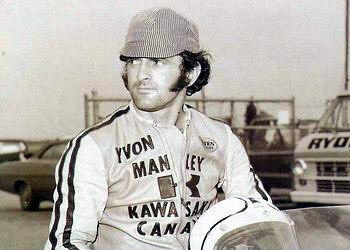
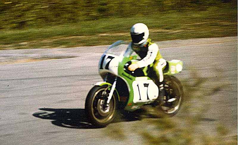
I worked for the Kawasaki distributor for Canada in the 70's called F. Manley and Son's or Manley's for short. This was after the race team was disbanded but I always had favor with the early 1972 model H2r's that Yvon Duhamel (#17) and Chris Manley (#11) raced here in Canada. This was the version with spoke wheels, rear drum brake, and the classic Borrani/Akront style flanged alloy rims and the early H2r frame design.
Duhamel when he raced for Manley's
Chris Manley on the Manley's #11 H2r. (photo by Bill Petro)
Photo no longer availablepetro75.jpgwas on canadamotoguide.com
Well I had the Borrani/Akront rims, an H2 engine that was race proven, 38mm carbs and the vintage style 1/4 turn throttle, a steel square swing arm and a H2r fairing. So I scored a wind screen for the fairing and a H2r tail piece and all that was required was the design plan to make a bike that looked like an H2r.
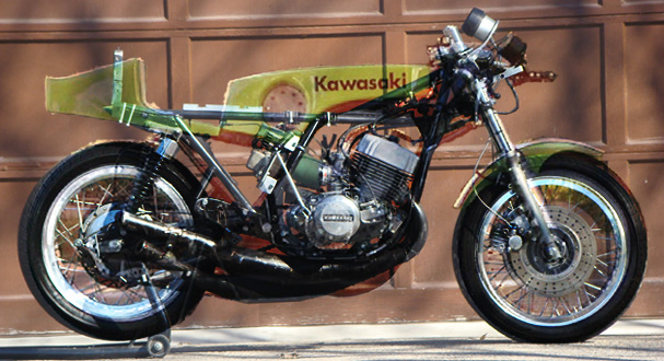
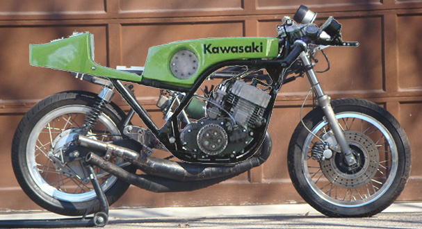
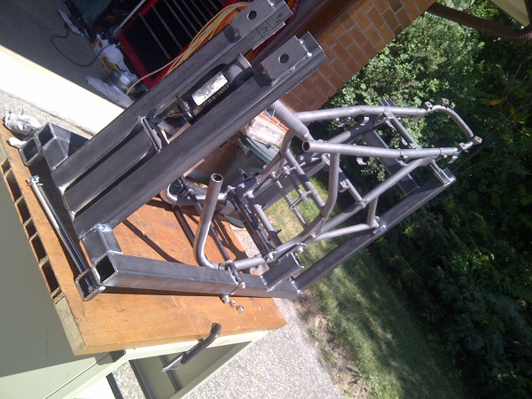
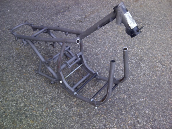
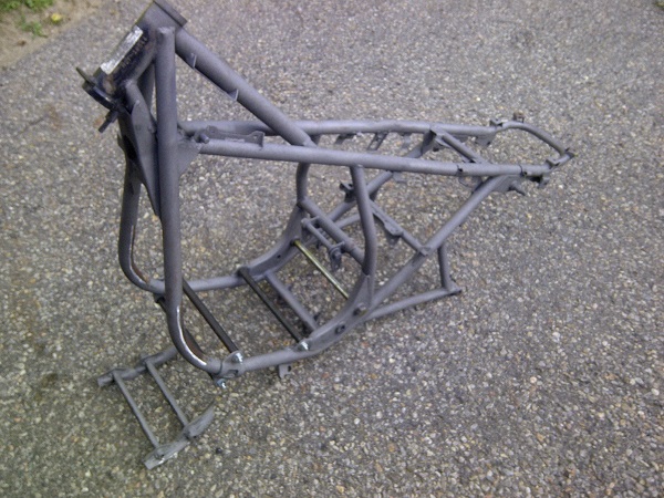
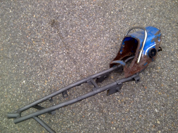
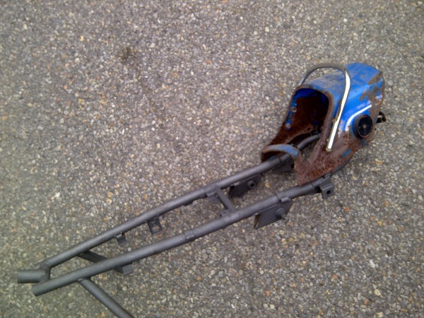
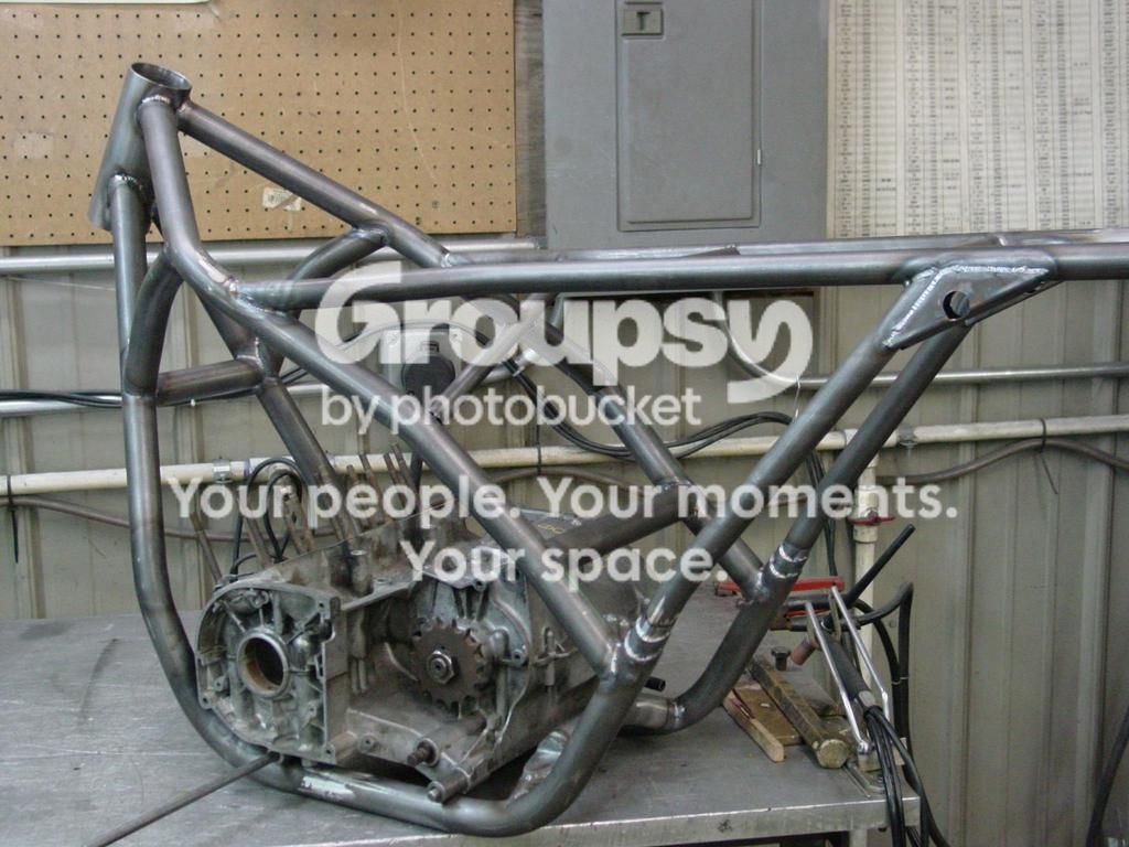
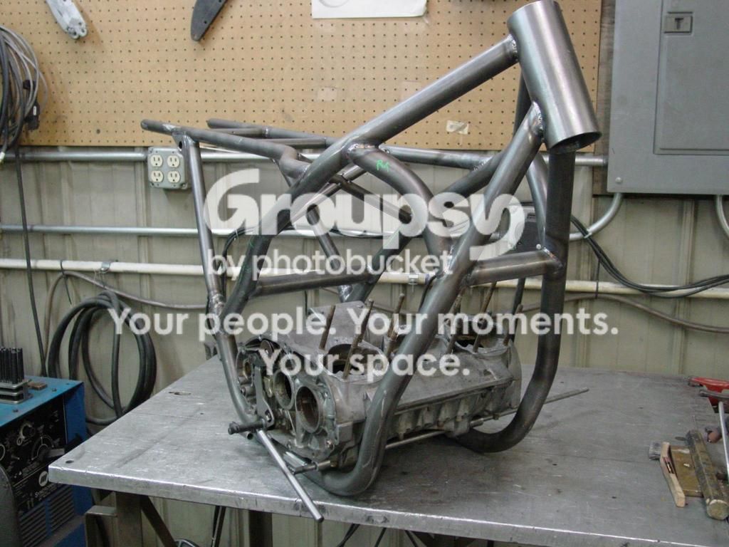
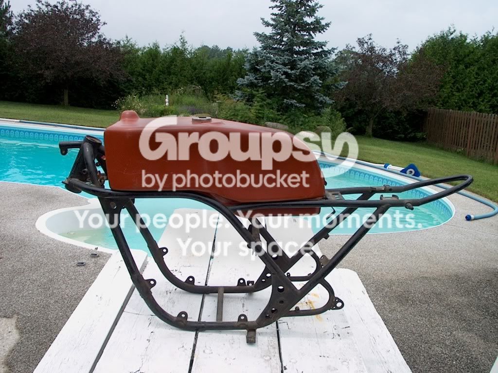
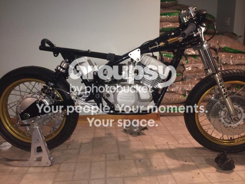
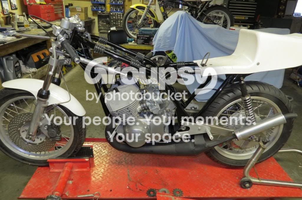
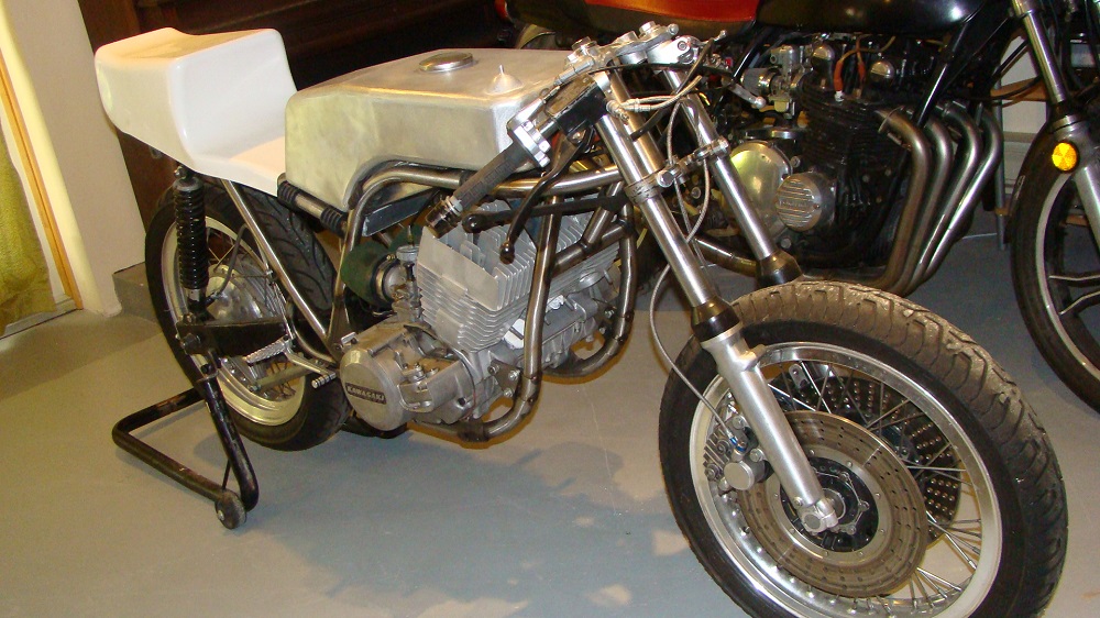
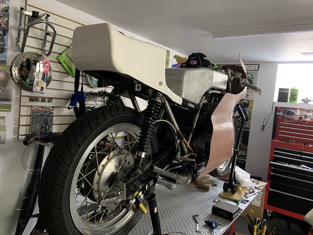
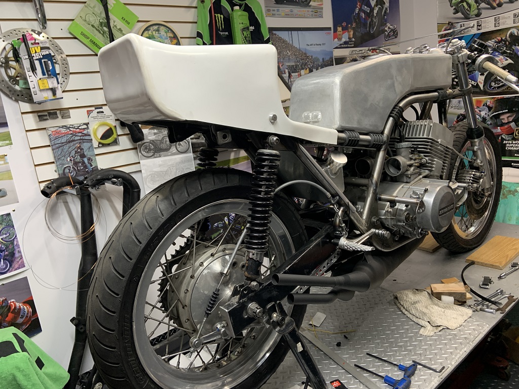
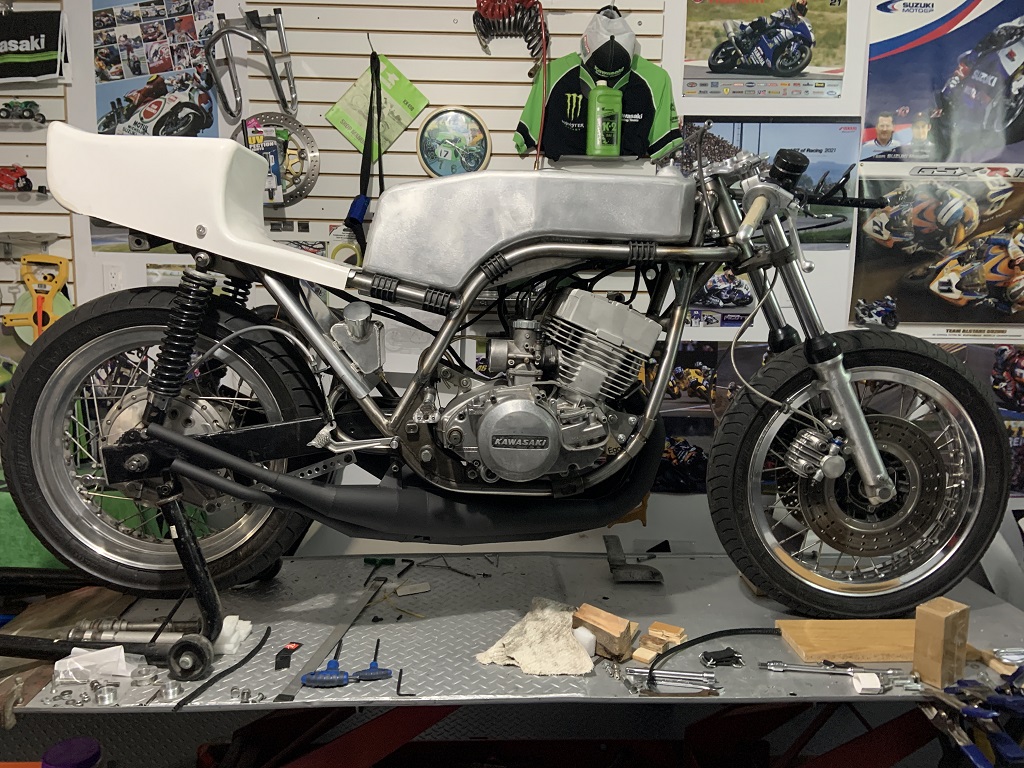
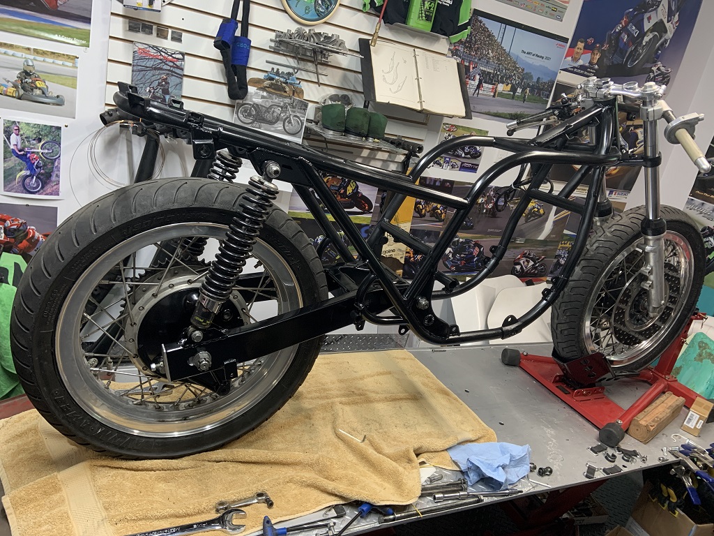
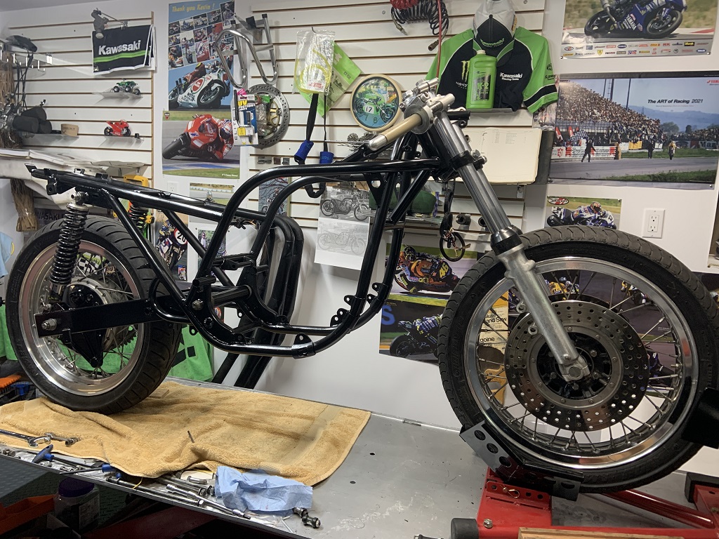
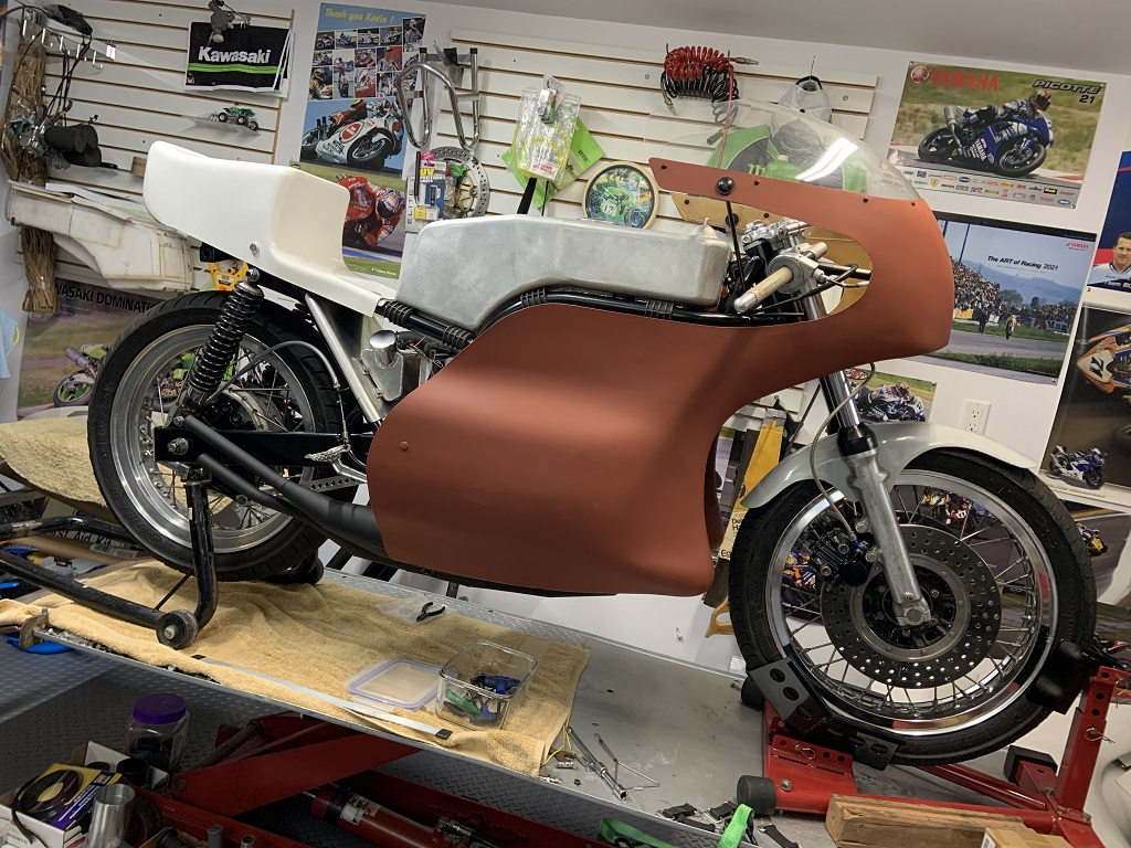
This is what I had to start with:
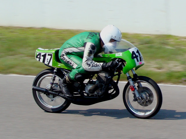
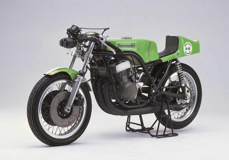
So how do I make it look like this? Here's a picture of one of the early model H2r's
I looked at the assortment of tanks that people have used on the stock H2 frames to build their H2r replica's and I found that without the shape of a real H2r tank it would never look like a real H2r.
Short of making a H2r frame, the next step was to see what I could do to the stock frame to make it look like the H2r frame.
So I super imposed photo's of my bike over the H2r photo's to see what (if anything) matched to the stock frame and dimensions. After checking the photo's carefully I could see that the upper portion of the frame would have to be cut away and replaced with the modified structure.
The good news was that the angles and dimension of the stock frame were useable as you can see in the photo's.
My Bike as it was.
OVERLAYS.
So the BIG question was, How Much Work Would It Take to Do This?.
Well I know I needed a steering head for this new frame. So I ordered some tapered rollers from Andre and off to the machine shop I go.
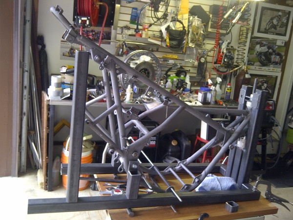
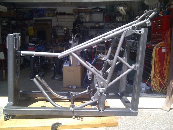
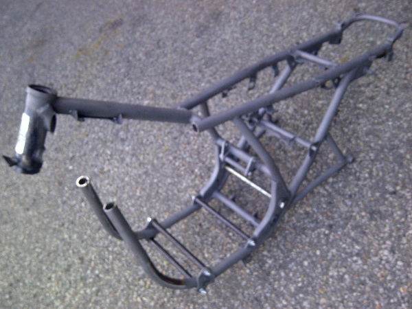
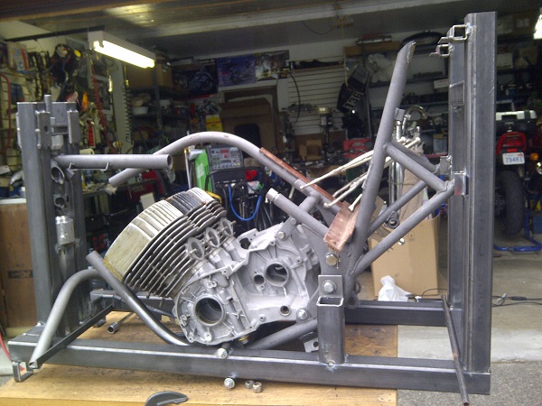
Then it`s, Into the jig with the frame and the new steering head and were ready for tube,.
Next was to get some tube and bend it.
Well I gave Nick Kemp a call. Nick was the Manley's Kawasaki factory race team mechanic on the H2r`s and Nick says ` You know I built a frame Jim` just get some tube and bring it over.
Like I said earlier, No Problem eh! 😁.
So I buy some chrome moly and off to Nicks shop with frame and diagrams I go.
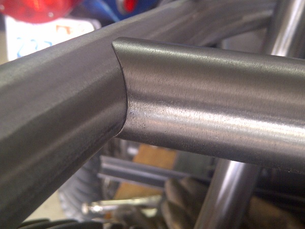
This was truly a big break as Nick found the die and helped me get the bending spot on. Thank You Mr. Kemp...
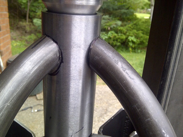
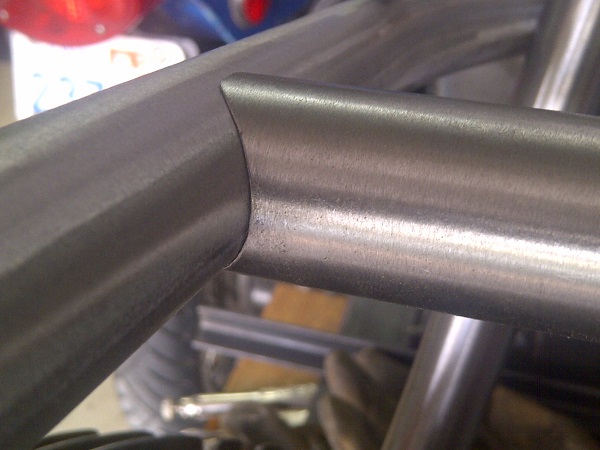
The real tricky part is getting the compound angles correct so all the contact point meet with the frame tubes in the right location.
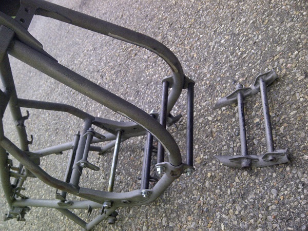
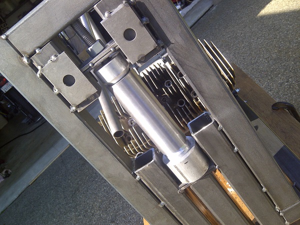
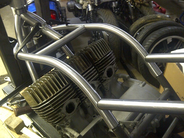
To replicate the H2r cylinders with the pipes inside the frame the right and left cylinder have to be reversed. The exhaust port angle now points toward the center.
I am Jorgen Lund, aged 41 from Norway. I have the past few days read about all there is on your board, and find it very interesting. I've learned a lot.
And this project is definately something I will follow very closely, as a H2R replica is a dream of my own.
I have 2 H2B's, 1 of them beeing a cafe racer. Hopefully finished during the cold winter. We have same climate as you guys. Have reached the magic 100rwhp with this one but struggles with a severe flat spot at 2/3 rpm of max torque rpm. This bike has a modified replica H2R hanson rear end and modified jollymoto pipes among other things.
I have an ELR with 1160cc big bore kit,a RD500 and a extremely funny riding 35 rwhp 1971 F8 Bison. (homeported 350cc F9 cylinder with squish band head and 34mm PWK copy carb).
WOW! Jorgen, you have all the bikes I want. 😁 The 350 Bighorn F9 was raced in Canada and the USA back in the 70's as it qualified in the 250cc class. Dave Crussel is from the USA and he runs one in the vintage races over here. It has a H1r style frame. Not sure if you had them over there. (Photo below). Several of our KTC members here are Z1/KZ fans so the ELR is a popular bike over here.
You should start a project thread here and post your pictures. I'd like to see the Jolly Moto's on the road racer.
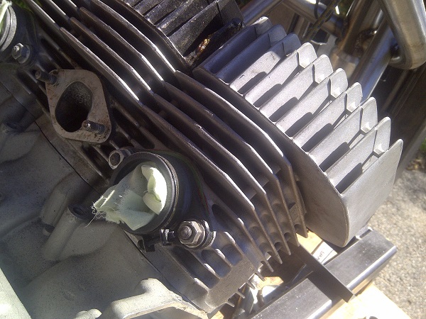
I'm right in the middle of doing some mods to the heads that Neil passed on to me. It's just a little different idea I had. If it works I'll post it as I get the build thread on line.
Nov 18, 2013 13:42:04 GMT -5pipe welder said: WOW! Jorgen, you have all the bikes I want. 😁 The 350 Bighorn F9 was raced in Canada and the USA back in the 70's as it qualified in the 250cc class. Dave Crussel is from the USA and he runs one in the vintage races over here. It has a H1r style frame. Not sure if you had them over there. (Photo below). Several of our KTC members here are Z1/KZ fans so the ELR is a popular bike over here.
You should start a project thread here and post your pictures. I'd like to see the Jolly Moto's on the road racer.
Yeah...maybe I should start a thread like you say, instead of ruin yours with my talking.
By the way, I did a search in your project category. WOW. You guys really have built quite some spectacular bikes!!!
What are you not understanding? Sorry if I wasn't clear. The Wall thickness .095" Material is 4130. It could have been thinner but the id. would not match the stock frame where I needed to join. For the few feet of material used in the project, the weight difference over thinner material is not a concern.
Nov 19, 2013 18:48:12 GMT -5JA-Moo said: It's all cool. I'm removing all the .095" I can to replace with .065", which is more than enough for a frame. To me, it's free HP........
Different strokes for different folks! 😉
I think Jim's goal is accuracy relative to the proper h2r. It's not gonna be a perfect reproduction, but it'll be pretty close. 🙂 Maximum HP/performance isn't the goal here. 🙂
Unless I messed up on my factorin' The weight difference would be about 1.5 Lb. between the two. What was Fat Ba$tard's line? "I've had a CRAP bigger than that Laddy!"
Probably closer to 2.5 lbs but who's counting. ( 2 craps) 😁 Then we have the steel (not alum.) swing arm, oh and on the real stupid side would be to use the H2 rear brake drum Da da da da..... and you got to wonder why Team Hanson didn't drill those front disk back in 73.
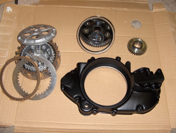
The Dry Clutch Discussion
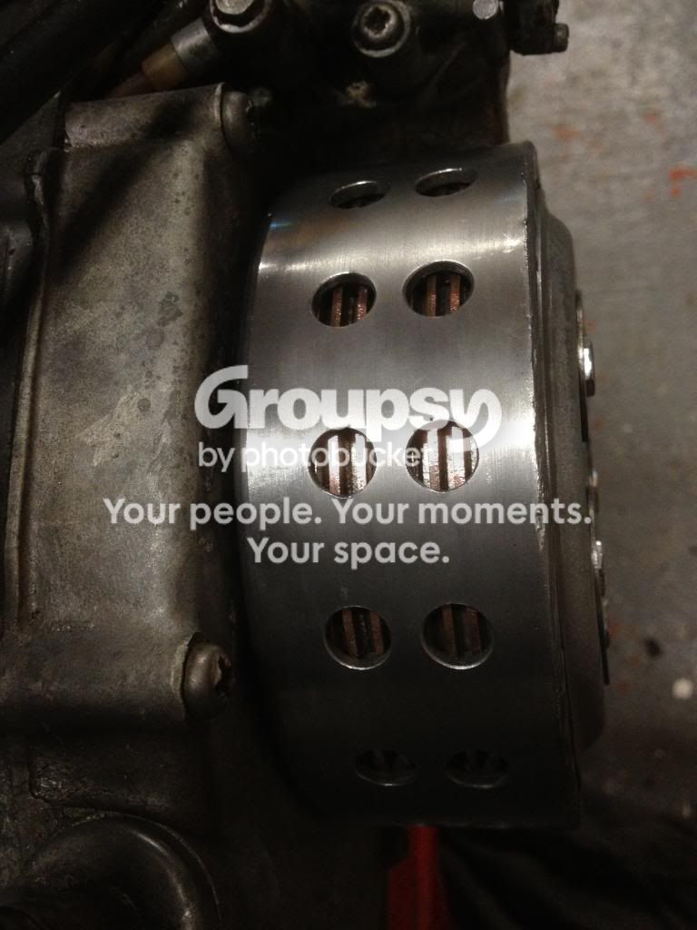
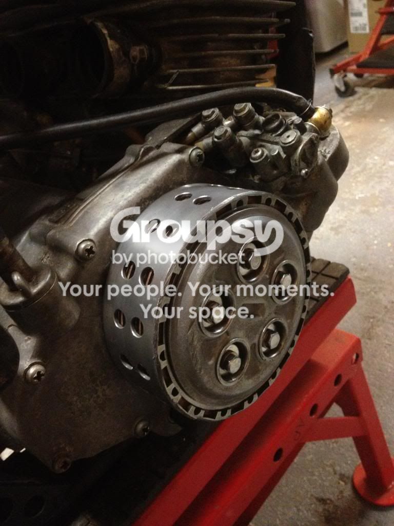
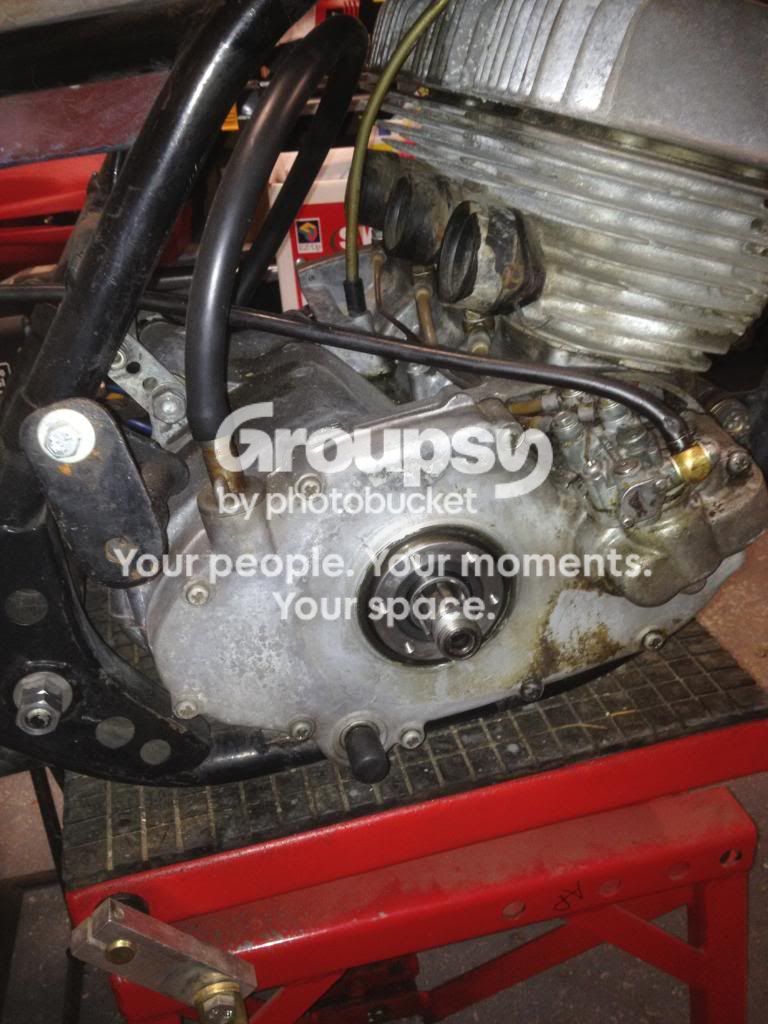
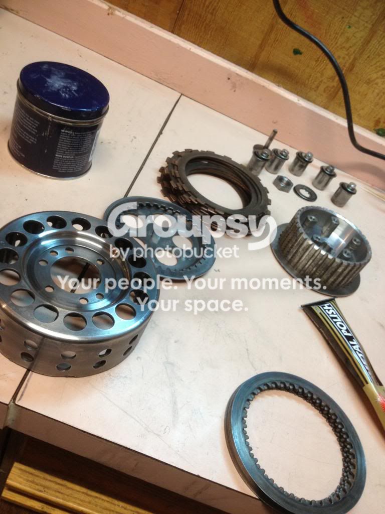
What I really need to know is who may want to sell me all the bits for the dry clutch. You never know. Could be one out in someone's shed somewhere. (yea right!)
I saw an S2 track bike (I think Brad has seen it too) that had a dry clutch set-up. it was pretty cool and had extensive welding on the cases. It looked like a lot of work for a little bit of cool - might be easier to cut out the centre of the clutch cover and put in a plexiglass circle. I've seen a picture of that and it's pretty sweet.
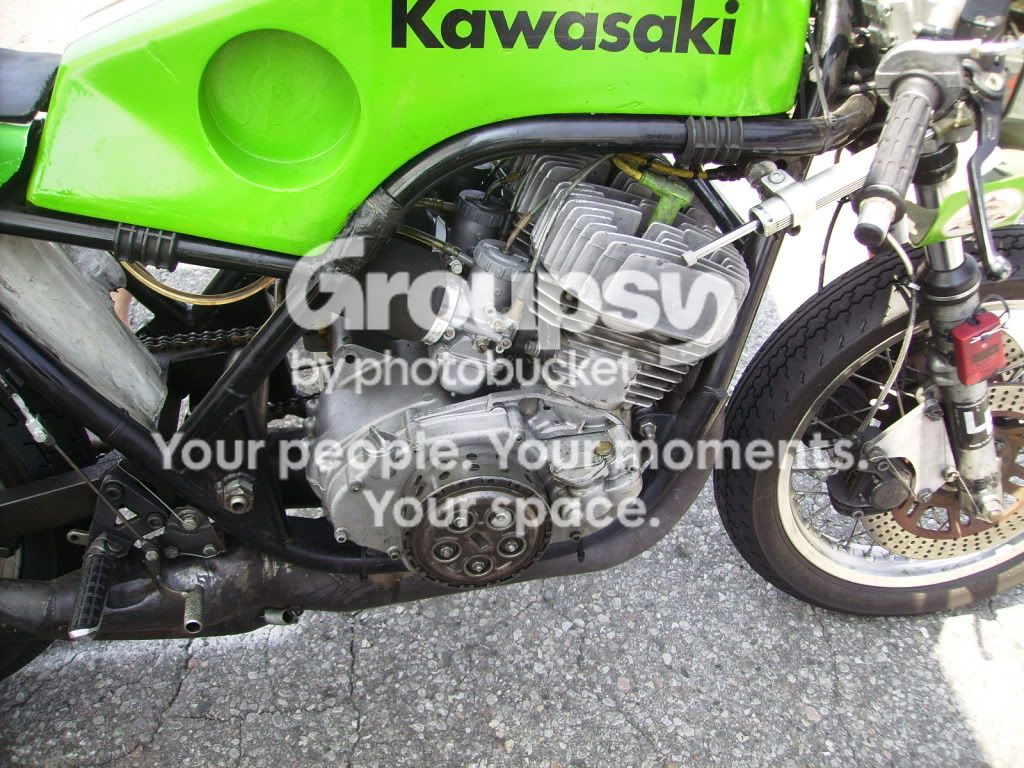
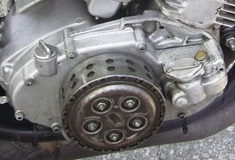
I saw some pictures of that S2 Ian. There is also some pictures out there of dry clutch setups that use the stock right side engine case. Like this one.
I don't think I would go to the trouble of making a dry clutch setup that used the stock case as it really doesn't look like the H2r clutch. That said, If I could get the Kit with the cast case, that would look very interesting.
For me to move ahead I need to source some rear sets, and get going on the fuel tank.
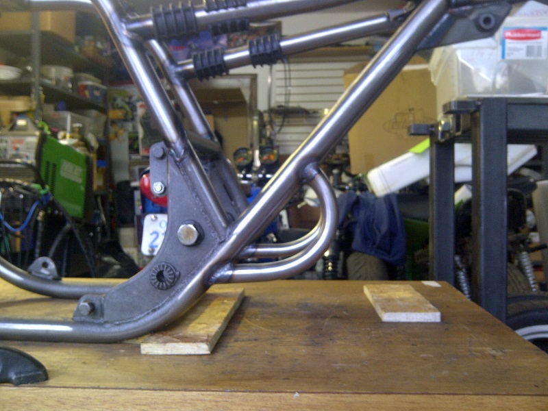
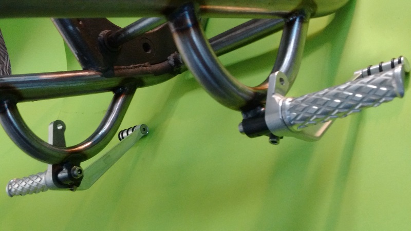
I would like to finish welding the rear set mounts so I have some decisions to make. The H2r had a small loop on the frame made of tube for the foot pegs and I may do that but it's real old school. I also had a look at Drewski's pegs on the Mongrel, They look like a nice set with a simple mount.
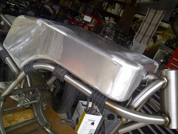
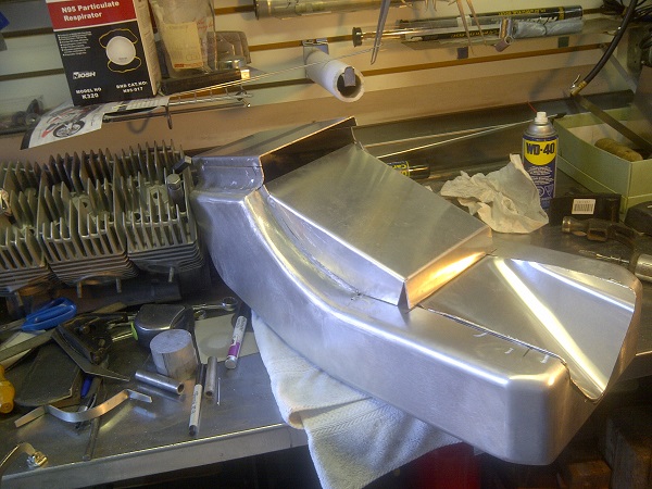
As for the tank. I'm going to take a shot at building one with aluminium. If I bought an Airtech tank it would probably have some fitment issues due to the dimensions I used for the frame.
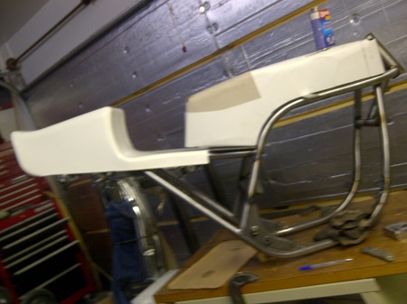
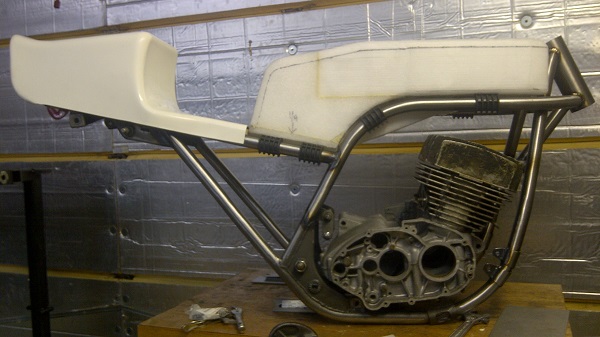
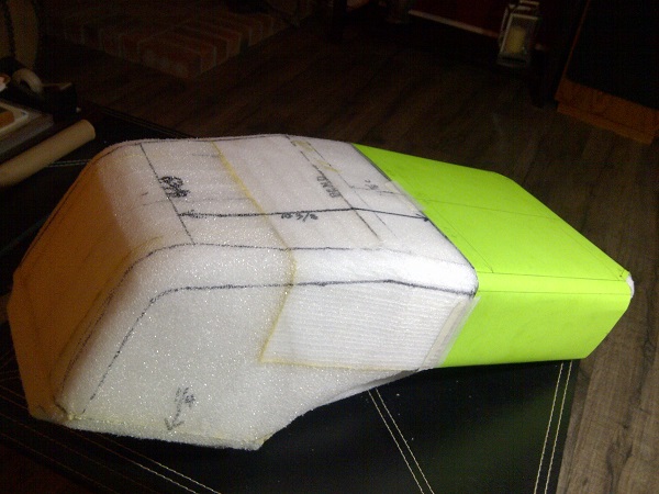
The only way to start building the tank is to first get visual perspective so I mocked up a shape from cardboard.
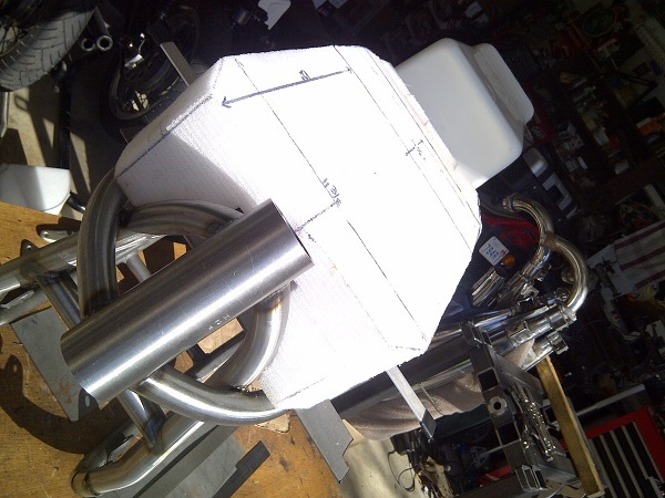
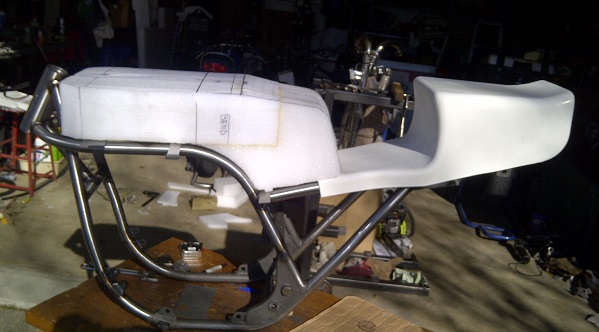
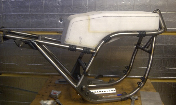
Next I needed some real measurements so I decided to work with foam to make up a mockup of the tank that I can verify fitment and clearances with.
Next I ordered the rubber tank dampers from Andre and started to trim and shape.
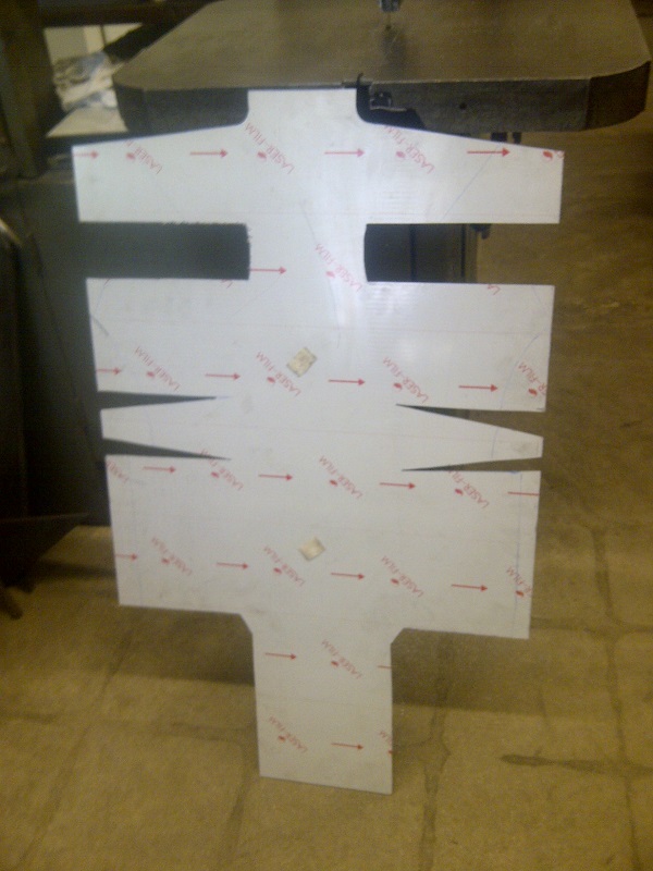
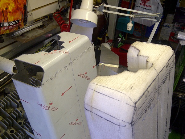
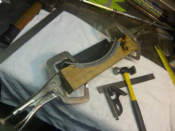
Now I have everything I need to make the templates that will be used to cut the aluminium.
Jim !! Excellent thread, When I saw you in Milton you talked about it, I was hoping to see more about it on this website.... Finally its here ! I thought about doing this many times, Even started building a tank mould, (Fibreglass) and did the same layover and stripped an H2 frame... But it all ended cause I got lazy ! Kudos to you man! As I remember there was also a chap in Italy that made a dry clutch set-up... Somebody will probably chime in on any info. The guy did not speak English so I had one of the guys from work ask him the questions. Looking forward to this build... The pressure is ON LOL
Great progress Jim. That dry clutch kit looks like a normal clutch cover that's been milled and had the kickstarter hole filled in? I know original dry clutches are pretty rare, but you have to admit they look cool. I like the look of the basket with the holes. Believe you need a different input shaft than stock as well. I'm sure it would take some decent $ to get someone to part with one. Here's Crussell's H2r from Mosport 2009. Could you settle for anything less? hmmm? I think you're going to need to make one Jim, first you need a bigggg piece of billet....
Maybe somewhat cool... The maximum recommended surface speed for high speed applications is 5000 FPM.... Most common seals are 1500-2500 FPM I'd say this seal is right at the 5000 FPM mark at full boil.
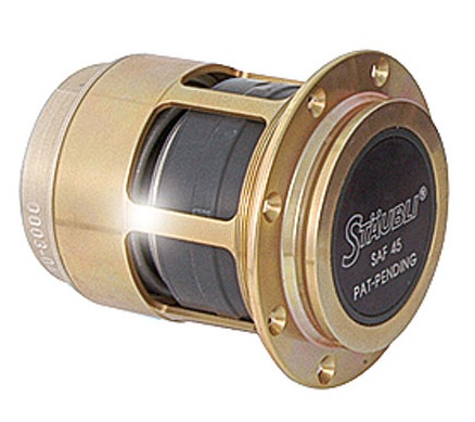
Have spoken to Ralf K in Germany, the open clutch comes as a 1700 euro kit, and are made in Switzerland. You may have a look at Ralfs Seeley H2 at youtube which has this clutch unit.
Looks pretty awesome so far! I agree that clutch doesn't quite do it. I'm not too keen on that giant seal, the real R clutches look like they are setup a bit better.
I've reverse engineered splined shafts and gears in boring mill heads plenty of times... This wee little shaft is no big deal. UNI gear in Montreal would make that sucker with their eye's closed.
Im pretty sure the 3D printers are capable of reproducing it, but have you ever seen a video of a hand gun made with one, exploding in the users hand?😕
Got to be a lot of stress on a high speed hub like that no?
Just want to let you know that the guys who made the clutch I referred to in Switzerland has a "R" engines in their shelf, also KR750. Ifg this was a easy go as John said.........well
Nov 22, 2013 22:56:12 GMT -5JA-Moo said: I'm telling you right now, it will be 100 times harder than anticipated. There is a reason they haven't been reproduced.
From my perspective, it's not rocket surgery, the only barrier is the want or need to pursue it.
No, it's not rocket science, nor is it as easy as scanning in a cover and 3d copying it. You could probably get your first test cover in under 15 grand......
I believe Ralfs set up was built my facing or narrowing the gears in order to separate the gear from the clutch housing to create a sealing surface. This is probably the easiest route to take. then you could build an authentic looking dry clutch cover.
To build it authentic The H2r clutch housing/basket is a special with a smaller 6 bolt hole circle that attaches to the gear. (the gear has a protruding sealing surface) That's how they got away with a small 64mm inside dia seal. So count on building a clutch housing and hub and the gear along with all other little tidbits including the splined shaft. That's a fair amount of work. Probably good reason why they are not reproduced... as far as I know.
However I do think you could squeeze the dry clutch cover between the gear and clutch basket and still retain the original splined shaft with a little creative machining using all stock parts and without reducing the gear width. It would be a cool project...
Well, as I've already said: Making a reproduction of the dry clutch seen on H2R can't be that easy since the guys in Switzerland I referred to earlier have NOS H2R on their shelf. Still, they choose to make the kit as seen on RalfK's Seeley H2. Why?
....the answer is logical as I see it: Too much work, at too high of a cost for production. Therefor they ended up with the kit to still an high cost.
Pipewelder, Nev Lush's comment about flipping the clutch gear makes sense.
Looking at an H1 clutch:
If the basket is detached from the gear and the gear is flipped there is now a 47+mm stub shaft available that will project out of a converted to dry clutch case. A properly shaped sleeve could be welded to this stub shaft and machined to increase it to Paulh's stated 64mm diameter (or larger if needed). The ID of this new stub shaft will have to be machined for a seal too. There would now be sufficient material to drill and tap the end of this built up stub shaft for the 6 bolt holes referred required to mount the clutch basket. The stock basket would also need to be reinforced/modified to accept the mounting bolts.
The case issue could be overcome by using a stock case and giving it the bandsaw treatment. A plate could be welded on to replicate the R case, including possibly a welded on boss for the 64mm ID seal. The case gasket surface would likely then have to be machined to eliminate any warping and the seal boss machined accurately in the appropriate position. File/machine the welds down flush and sand blast the modded case to replicate the R's sandcast finish.
Careful placement of case/seal/clutch positions should allow the use of the stock input shaft as reported by Lush.
It only takes lots of $$$$$ and a bit of imagination to make it work... A few pics of the various R parts would help too regarding the case/ basket/stub shaft interface area.
It was mentioned Dave Crussell is running a setup similar as I state. You may want to contact him directly for more info and possibly drawings of the needed re-work/additional parts.
A dry clutch certainly would add bling factor of your replica.
So there ya go Pipe welder! Our resident H1R owner was nice enough to "step up to the plate" to supply you the needed pics.
You have the welding skills/equipment to minimize the out sourcing costs. Are you willing to have a go at it and work around the 10mm shorter shaft, as others have done?
From about 1975-1978 I did not have a kick start lever installed (due to my rearsets the darn kickstart lever would eat into the side of my leg if installed). I could usually bump start the bike in about 5-10 feet with little effort. Got REAL good at not stalling/launching at the stop lights WITHOUT making allot of noise, which attracts the law...
Somewhere around 1979 I took the "Solidox" to the kickstart lever and bent it out of the way. It also would now clear the pegs/brake lever etc. when used....
My belief is you need to separate the gear from the basket by approximately .300" via a hub . .250" for the seal and around .025" clearance per side. Simply by counter boring .150" deep from the inner clutch face (nut side). The other .150" comes from shimming and machining the clutch gear stub....but that's where it gets tricky and you gotta get your fingers in there and see with your eyes and start to build instead of sitting on warm couch dreaming and scheming like me lol.
No matter how you do it... or think you would do it ,,,, There is a huge inherent risk with altering these components. If the clutch lets go...loosing a leg or your middle one while leaning on a hard right. lol
You could build a replica clutch basket like the H2R and bolt it to the dry clutch cover. (Scatter shield)
For a few guys to get together and build some for themselves !! Great !! but to sell it... Way to risky.
The dry clutch cover. I was looking into this a few years ago.... Making it the old school way with a copy milling machine. start with a billet of aluminum and a stock clutch cover. It is really simple to build except for the outer areas around the tach drive. No need to scan an original cover and develop a CNC program. I spent about 5 years on one of these machines and the possibilities are endless. One off parts and or copying existing parts was a dream. Unfortunately I do not have access to it any more but they can be had relatively cheap. There is one on kijiji for $2500 but not the right type.
Provided the friction plate tabs don't bottom in the basket finger grooves, you may be able to trim a bunch from the engine side of the aluminum clutch hub (as .030in typically done for the H2 extra plate(s) mod) to further reduce shaft length requirements. Using a stock H1 fiber (or H2 if they have the curved tabs) as the first plate installed (with its curved tabs pointing out) would allow further sinking of the hub within the basket..
Nov 26, 2013 19:33:14 GMT -5lc said: So there ya go Pipe welder! Our resident H1R owner was nice enough to "step up to the plate" to supply you the needed pics.
You have the welding skills/equipment to minimize the out sourcing costs. Are you willing to have a go at it and work around the 10mm shorter shaft, as others have done?
J
I think it would be great to take this on. Your method to replicate a case by welding in the center section and blasting the finish for the sandcast look sound very do able. As far as the shaft goes, if I was to go ahead with this in the future I think Walms has the right idea to manufacture a new shaft to spec. I know people with vintage race cars who have done several shaft reproductions. As Andrew said you just need the contacts, design and the right shop to keep the quality and costs in line.
It seems clear that the required information and skills are available right here with you guys to do this and I certainly would not consider doing a dry clutch build on my own but.
It's got me thinking. It would be an entire project on it's own. MORE WORK NOW! 😁
OH and thanks for the great pictures Sooperarthur!...
Due to the configuration of the integral 1st gear the shaft you refer will be exclusive to only an H2 gearset. As such a one or two off will likely be expensive regardless.
Considering what paulh stated earlier; I reviewed the areas to modify as per Lush and 'tuner posts last night while looking at the primary gear installation on an H1.
With thought the primary gear set can be moved inbd about 1.5mm+. Selection of an available narrow case seal (and making the 6 hole gear stub shaft the required OD) along with 'tuner's quoted reductions of the stock parts should allow using the stock length shaft.
Thanks for the compliments Paul The fitment issues I ran into were a lot more than I planned for.
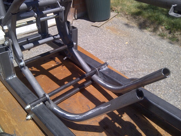
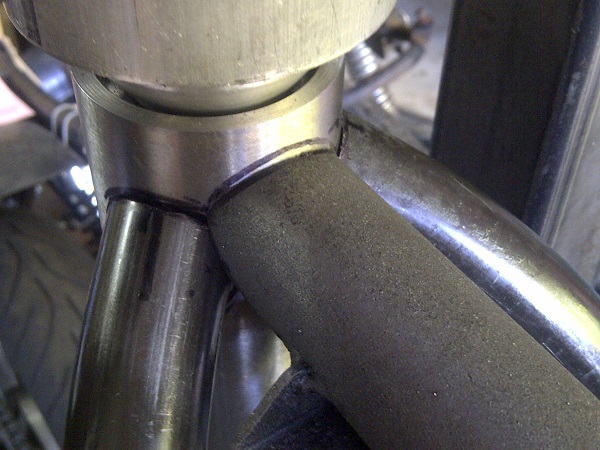
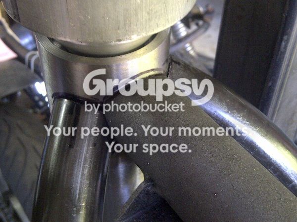
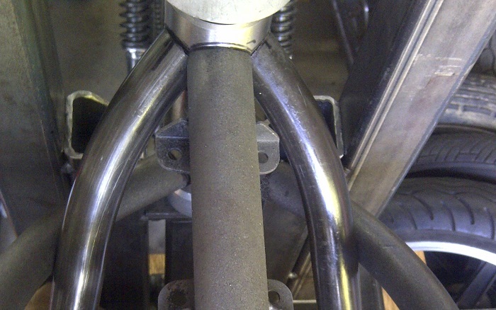
If you look at the photo below that was taken from above you can see that the two tubes that go down from the steering head must also touch the two tubes that go under the fuel tank to the lower part of the steering head.
I realised when I got to that point that there was no way for me to calculate these tube lengths in advance. Each tube had to be trimmed and put into place many times knowing if I take off too much length at the steering head they won't contact below and would be scrap.
Just as well that I didn't know what I was getting into or I probably wouldn't have started it. 😁
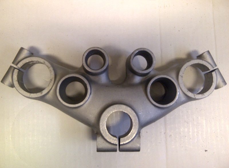
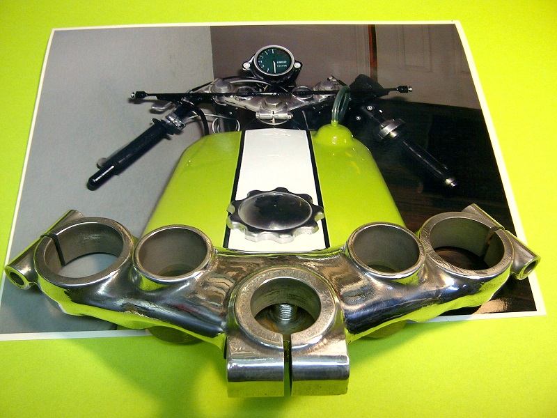
Who has the hot tip on how to remove the black paint from a stock upper triple clamp?
Given that I want to polish it up to a dull aluminum finish I have been told several different ways to do it. Sandblast and polish, brush on paint remover, buff it off. I understand the stock paint is tough stuff. Any of you guys have some experience with doing this?
I've never done an upper triple clamp, but some of the brush on gel antique paint and varnish remover is great stuff. If it was me, I'd give that a try first... 😎
... or brake fluid!! That kicks the crap outta any painted surface I'VE ever spilled it on!! 😆 🙂
Who has the hot tip on how to remove the black paint from a stock upper triple clamp?
Given that I want to polish it up to a dull aluminum finish I have been told several different ways to do it.
I bought a spray bomb of stuff called Aviation Remover, made by Rustoleum I believe. Stripped some nasty old paint that Zip Strip had trouble with. Not cheap, but effective. Got it at Wally World too. Jim, I'd say a good stripper like this and some elbow grease would give you what you're looking for.
If your going for a dull look, why not scrape off then give it a quick and dirty polish job ? Any small amount of time on fine wire wheel then to polish/buffing wheel should give you that result
Don't sandblast, creates way too much work. A good few sprays of aircraft paint remover and a pressure washer. Then you can scuff it with wet sand paper say 1200 grit and a quick " half assed" polish.
Circa 1850 paint and varnish remover Bud. This stuff will strip paint and varnish off of anything, and it cleanes up with water. You can get it at just about any hardware store or Canadian Tire. Brush it on, let it sit for a few minutes and then a scrub with steel wool should do the trick 😁
My vote goes to the Circa 1850 paint remover. I used it successfully on the upper triple clamp on my H1, among other things. Brush on, wait a few minutes, rinse off - it's that easy 😎
The lower was bead blasted and the upper stripped with Circa 1850. The couple of dark spots visible on the upper clamp are where the paint was chipped, so I guess more heavily oxidized. My initial intent was to strip and repaint but I liked the bare look so much that I just clear coated them.
Dec 18, 2013 11:41:47 GMT -5ballvo said: My vote goes to the Circa 1850 paint remover. I used it successfully on the upper triple clamp on my H1, among other things. Brush on, wait a few minutes, rinse off - it's that easy 😎
The lower was bead blasted and the upper stripped with Circa 1850. The couple of dark spots visible on the upper clamp are where the paint was chipped, so I guess more heavily oxidized. My initial intent was to strip and repaint but I liked the bare look so much that I just clear coated them.
Well I picked up a can of that Circa 1850 striper and you were right Daffy. Just like Neil's clamp, striped the paint right off.
It really was impressed. Started pealing within a few seconds. I used a small paint brush and when it was all flaking off I washed it off with water and did it a second time. No stink no mess. Super easy job. I can't believe how good it worked.
I think I may try this stuff next time I need to strip a frame. It seems to be way better than sand blasting but I would probably have to wash it off with coolant from the lathe so the steel frame wouldn't rust right away. Should work good.
Thanks for the idea guys.
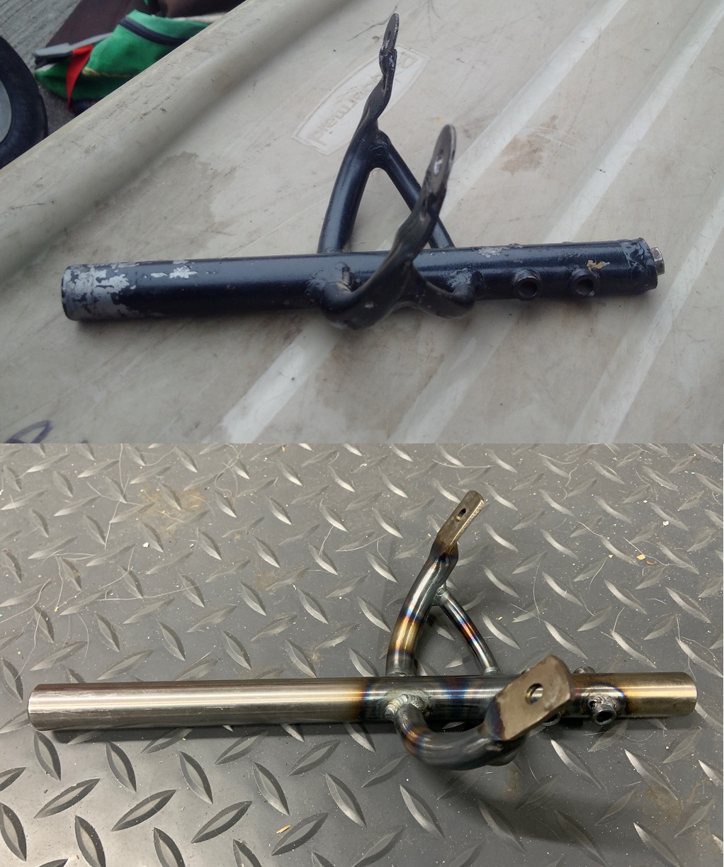
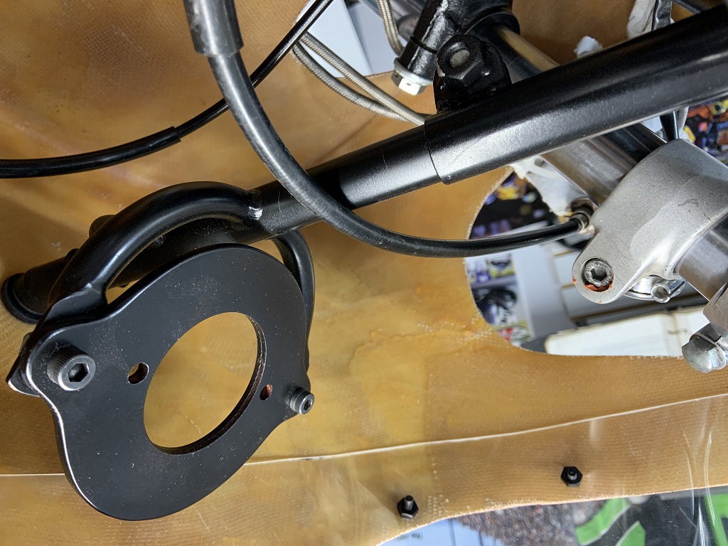
Time to cut off the instrument mounts and clean it up with a light polish.
That stuff eats through everything. For furniture re-finishers, it eats through half a dozen layers of a variety of paints... no sweat. It's amazing stuff. 😎
I cant believe I was parked just above you guys in the trees! I never walked down that way !, Good to hear your bikes coming along, looks fantastic so far, I really enjoy your build... so keep posting!! Been doing some testing on the 516 but keep getting sidelined with work, kids, family and kids with broken cars, and other stupid things that I just cant say NO to..lol.
I would like to finish welding the rear set mounts so I have some decisions to make. The H2r had a small loop on the frame made of tube for the foot pegs and I may do that but it's real old school. I also had a look at Drewski's pegs on the Mongrel, They look like a nice set with a simple mount.
As for the tank. I'm going to take a shot at building one with aluminium. If I bought an Airtech tank it would probably have some fitment issues due to the dimensions I used for the frame.
The only way to start building the tank is to first get visual perspective so I mocked up a shape from cardboard.
Next I needed some real measurements so I decided to work with foam to make up a mockup of the tank that I can verify fitment and clearances with.
Next I ordered the rubber tank dampers from Andre and started to trim and shape.
Now I have everything I need to make the templates that will be used to cut the aluminium.
I've had the rare privilege of seeing this project progress from nothing more than an idea, into what Jim holds in his hands today. It actually took so long to get started, that I wondered if he ever would. Start it he did though, and only those who've attempted fabricating something like this will really appreciate all that has gone into this project... 😎
... and this is just the beginning!! 😮
Stay tuned to this thread to see what Jim has "up his sleeve"! Haha! 😄
Jim might drive some crazy with his endless questions and thousands of pictures from umpteen angles... but he has a vision and a plan. The plan may take some twists and turns (what plan doesn't!!), but he'll make it to the end. 😁
Airelman said: So Jim..Why aren't you done yet..Stop sitting down drinking from that Growler man 😁 looking REAL good Jim
It's not my love of beer Ian (Well maybe a little. 😉) I'm trying to get fired from my job so I can have more time but it's not working....Lol My wife who is my boss just seems to put up with me. 😁
Truly though, this stuff take a lot more time than people realize. It gives you a real apreciation for other peoples prjects.(Like yours Ian.)
Nice work Jim! I remember looking at your pictures in Tweed last year and thinking, even with visual aids I still can't understand the process. The more I see, I realize the less I know. 😕 Now I want to sign up for a welding class at night school!
I think one of the things that's so cool here is that because Jim researches and thinks things through so well, he get's it right the first time. 😄 I know a few guys (me included!) who would have a dozen expensive door stops/paper weights trying to fab something like that!! 🤣
Just make lots and lots of card board proto types first before you take the plunge. That's my opinion. But then again, after my 1st glass tank, I had a tank builder make my fuel tank for me 😉 I still couldnt come close to this tank on Jims bike though. Some people have the skills, some, like me, just look on in awe. Nice work Jim 😎
Spinning the insert would be the way to go for sure Walms. I assumed that might be expensive. If you want to ask your contacts about it some day I would like to hear what they say
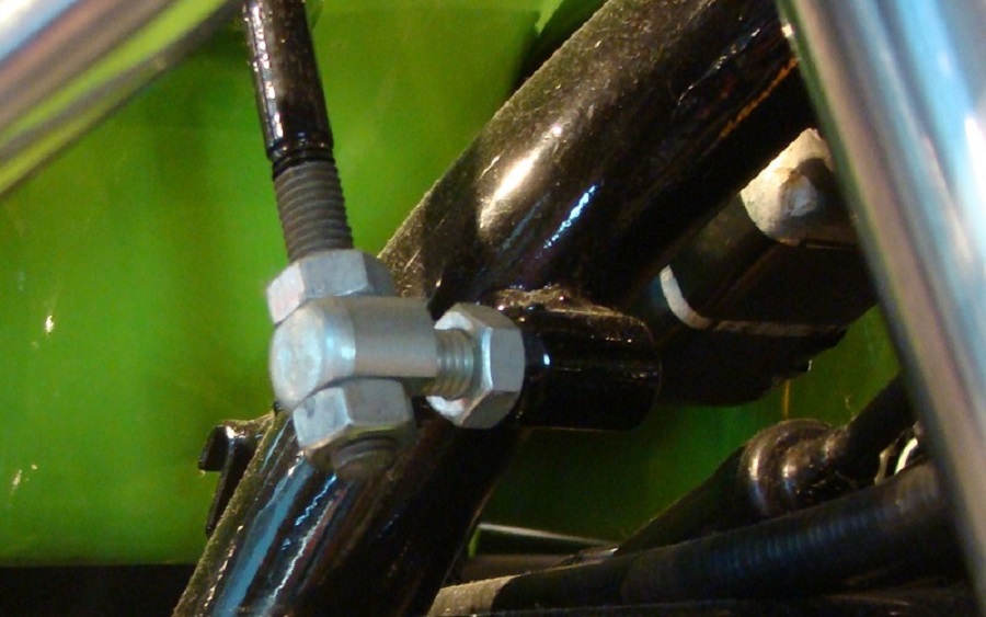
Part of the challenge here is the fact that the rear brake is cable operated and the break leaver will need to have a cable mount.
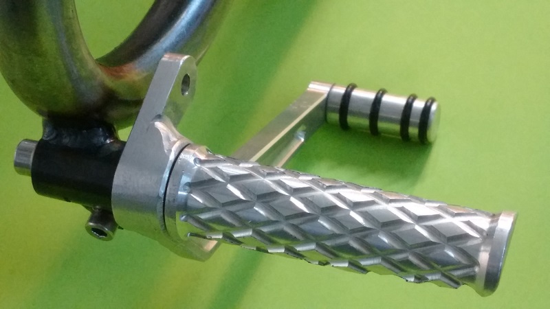
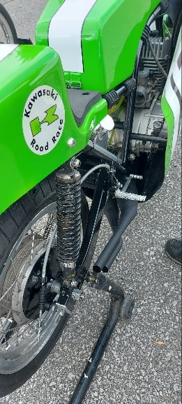
Not really liking what I found for rear set kits and seeing that most of the available kits would require modification Nick came up with some rear sets that he made and I did some adaptation. These same pegs were used on the H1r that Nick built.
After I put the engine in place and get the rear wheel mounted I can check the lever angles and the moment arms which may need to be modified.
Pipe welder, have you considered using a rod instead of cable between brake pedal& rear drum? Less authentic but maybe stronger and easier to do? I used 1/4" SS round stock on my KH500 when I went to rearsets without much trouble...very nice work on your project so far, eager to see the finished product!
As far as pipes goes Paul, I'm hoping to find the time to go for lunch one day with Lc and Henry and have good look at Henry's original H2r and the pipes he has. I also spent some time about a year ago talking to Walms about making a set with a modified header section that would follow closer to the path and shape of the original H2r pipes. Mr Walms can do amazing things and I just have to weld it up. 😁
I sure look forward to seeing those pipes hangin out behind a green fairing one day!
Jim, if you have time to weld them, the segment number could go up to be less faceted. Were you thinking of making the pipes for H2R spec? Just throwing it out there but the sweeping H2R pipes look like something that could be hydroformed.. I have something I'd like to try regarding that method Jim, if you are keen, let me know. 😉
Dec 12, 2014 17:17:46 GMT -5Walms said: Jim, if you have time to weld them, the segment number could go up to be less faceted. Were you thinking of making the pipes for H2R spec? Just throwing it out there but the sweeping H2R pipes look like something that could be hydroformed.. I have something I'd like to try regarding that method Jim, if you are keen, let me know. 😉
... and if you need any more practice before you weld you own...
Hey Jim,I don't know what rear wheel you are using ( I used an early H1 on my H1r)But this is a pic of the H1R rear brake set up.I used an early H1 cable & it was 2 inches short using the stock H1R mount on the frame as shown.Hope this helps. Brad
I just use the pic so he could see the set up.As I said,I used an early H1 cable & it was a couple of inches short.To use an H1 cable he will have to move the mount further down the frame.I did not want to alter my frame so I used a piece of flat stock to get the length I needed.
Walms, Hydroforming the front section of the pipes is something I've considered but its off in the future. I can't do any test fitment on pipes till the engine is in and the fairing is ready to mount so it's still a ways off.
Brad, that picture is basically what I will have to make. I'm I'm using the wheels that Rudy had on the race bike. Their not perfect period replica's but their going to have to do.
reimeir confirmed the length on the H1 cable and it looks like that's what I need. The one I have is 24" and it's too short. The H1 cable is 29" so I have to get one and make the mount on the frame as per your photo.
Dec 13, 2014 9:24:58 GMT -5Walms said: Will Henry loan you his pipes for reverse engineering? A good question to ask over lunch after you pay the bill. 😉
Good point Andrew, I could make a quick sketch with the measurements on Henry's that would be quite accurate. I'm also interested in getting a head profile for the squish.
I just made a port map of my cylinders and I'm sure my porting will be different from the H2r. Nick confirmed that they had several sets of cylinders for the H2r's with different porting that were designed to be used on specific tracks. For example, Mosport being a high speed track with an extremely long up hill strait required porting that produced as much HP as possible but would thus suffered on some midrange. That was suitable for that particular track but probably was not ideal in a twisty lower speed track with shorter straights where they also used a much lower final drive ratio on the gearing.
Nick gave me some maps from Duhamel's motor and I plan to go over some different maps with Lc as porting is a weak spot for me. I would like to compare to Drewski's and Zambia's FBG/drag engine maps just to see and learn also.
Henry is a great guy ad I feel privileged just to be able to talk to people like him who are just a wealth of knowledge on this stuff.
If you can lay the pipe on a large piece of graph paper and take a picture square as possible at maximum zoom, I can scale that picture in Solidworks and be able to replicate the sweep of the pipes to be pretty accurate just from that, at least close enough for the first mockup, then tweak from there.
Jim, fwiw I received an order from Frame Crafters for a set of pipes on a H1R with reversed cylinders. He was planning on modding an existing kit of mine but I was thinking I might be able to nip 2 in the bud. I'm confident I can make a design that works well on both motors. I thought you'd appreciate these shots of his project.
Mar 11, 2015 19:25:23 GMT -5Walms said: Jim, fwiw I received an order from Frame Crafters for a set of pipes on a H1R with reversed cylinders. He was planning on modding an existing kit of mine but I was thinking I might be able to nip 2 in the bud. I'm confident I can make a design that works well on both motors. I thought you'd appreciate these shots of his project.
Interesting frame but a long shot from an H1r.
I will be trying to get my pipes to look similar to the shape of header pipes used on the original H2r. (see below)
This is North's H1r frame.
H2r header pipes shown here with the steep angle near the exhaust ports then strait down and then close to the frame to leave room for the full fairing.
Also, he never claimed it was a replica, just that a H1 was going in it... Actually, his design looks more efficient than the H1R side by side. I should ask him about the weight of it.
Are you referring to the down tubes just aft of the steering head? If so, this is the part I like about the frame, they shorten the backbone and will help quite a bit actually.
Mar 12, 2015 14:44:10 GMT -5Walms said: Are you referring to the down tubes just aft of the steering head? If so, this is the part I like about the frame, they shorten the backbone and will help quite a bit actually.
I'm referring to the engine cradle down tubes. They can be made to fit the stock cylinder configuration or if it's to be "similar" to a H1r or H2r the outer cylinders must be reversed as you know.
860 choose to use the version of Dennis's frame that fits a stock engine and saved himself a lot of work on the cylinders.
What I was saying is I simply don't see why you would build a frame that requires the cylinder reversal if it were not meant to look like a H1r or an H2r. There are several proven race frames out there that do not require the reversed cylinder configuration. LittleGuys is a good example where he used a frame built by Lou Zeman and again no exra work to reverse the cylinders.
I can't answer that anymore than why someone would make a HR replica without reversing the cylinders? Maybe just to make a more rigid frame and cool factor? He does make custom frames for a living. 😉
I have just found and read this thread. VERY cool work sir. I am in awe of folk who can make such nice stuff. It looks real good.When you are getting to the engine/clutch bit, shoot me an email, if you need a tip or two.I am sure you have the skills to do a conversion, looking at the pics shown.
Hi Neville Thanks for your compliments and all the great comments and compliments from all the guys here on the board. It's very encouraging and I wish I could get back at the work.
As for the engine it will be last on the list. This was a running and raced engine so I plan to get all the other work done and run it in it's current configuration before making any other engine modifications.
I'm looking forward to the pipe work also. Should be interesting. 😉
Just credit where due Jim. All excellent work. From the research to the fabricating of the frame to where it is now. Pipes are going to be just as nice I bet. Good Luck
Aug 8, 2016 11:21:33 GMT -5pipe welder said: Hi Neville Thanks for your compliments and all the great comments and compliments from all the guys here on the board. It's very encouraging and I wish I could get back at the work.
As for the engine it will be last on the list. This was a running and raced engine so I plan to get all the other work done and run it in it's current configuration before making any other engine modifications.
I'm looking forward to the pipe work also. Should be interesting. 😉
Thanks again to all.
The pipes are the most fun, imo...with your skill, looking forward to see what you come up with 😁
What some of you don't know about is the years of research Jim put into this before he ever turned a wrench or fired up the welder. Jim has pics from multiple angles of every h2r he could get near or find on the web. 😮 He was at it so long, some of us wondered if he'd ever actually get to building it!! 😁
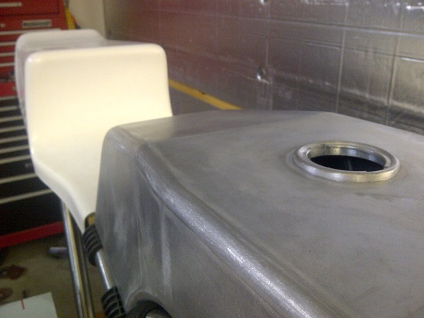
Well deserved recognition Pipewelder! You da man! 😄 😎 (Oh ya... that's my gas cap on the tank too. A MAJOR piece of the puzzle! 😁 )
Pipewelder has taken a bit of a break from this build. He and Mrs Pipewelder bought a 'country estate' that needed a little TLC, so that's been taking up the bulk of his time for the last year +. 😄
I'm on his case to "git 'er dun" though so you might see some progress this winter. We'll see...
May 20, 2018 19:36:24 GMT -5dneperformance said: impressive .found an h2r engine in a triple junk pile.not practical for street.cr tranny and dry clutch setup will not accecpt a kick sa
im new to this.ser#9138 had denco 792 in 1975.can not decide what to do.wanted a clone of my old bike but i can't imagine a push start street bike[lame 62 year old] paul gast suggested i sell my engine and buy a rider.any input on what to do would help .don@dne
May 20, 2018 20:17:23 GMT -5dneperformance said: im new to this.ser#9138 had denco 792 in 1975.can not decide what to do.wanted a clone of my old bike but i can't imagine a push start street bike[lame 62 year old] paul gast suggested i sell my engine and buy a rider.any input on what to do would help .don@dne
May 20, 2018 20:17:23 GMT -5dneperformance said: im new to this.ser#9138 had denco 792 in 1975.can not decide what to do.wanted a clone of my old bike but i can't imagine a push start street bike[lame 62 year old] paul gast suggested i sell my engine and buy a rider.any input on what to do would help .don@dne
Curtis, your all over this one. I didn't know you were going to start a H2r project. LOL
Hi dneperformance Thanks for the compliments. I would also be interested in this engine as it would have much of what I need to complete the project. I may have what your looking for to get a street machine back on the road. Contact me if you want to follow up on any possiblities. Jim
May 20, 2018 20:17:23 GMT -5dneperformance said: im new to this.ser#9138 had denco 792 in 1975.can not decide what to do.wanted a clone of my old bike but i can't imagine a push start street bike[lame 62 year old] paul gast suggested i sell my engine and buy a rider.any input on what to do would help .don@dne
Curtis, your all over this one. I didn't know you were going to start a H2r project. LOL
i this engine would interest .met duhamel oval racing skidoos in early 70's.own rotax performance shop.{dneperformance.com}.my typing skills limited by arthritis.shop located in orillia on.,moved it home 11 years ago to slow things down abit.haha.easier for me to use talktext 705 790 0764 or call.don emery @dne.
It’s been a long time on this one but the project is back on the go.
After 5 years of other issues including building a work shop this bike is back on the bench. A big thanks goes out to Walms for working out a custom pipe design that is ready to assemble and we’re moving ahead.
Been out of the loop for quite some time Jim, but wow man this project is something wonderful. Custom fabricating is a tough road if you don`t have the skills, but you`re definitely killing it. Unfortunately my bike days are over, suffered a heart attack back in Aug 2020, and was advised to stop riding, as any major adrenaline surge would not be in my best interest. 😢 So sadly I`ve let all my bikes go to new homes, and most recently with lots of tear, I broke ties with my Guzzi.... Hope to see this bike in person some day, Cheers
Hey Perry. Thanks for the compliments. So sorry about the the health problems. We never know what tomorrow holds for us.
As a word of encouragement I just spent today at Mosport with a very good friend who had a major attack. He was in bad shape but nevertheless kept working on his recovery and re gained his racing license and his living large.
All the best to ya Perry. I’ll try to get to visit ya. Lots of great times we had. Jim
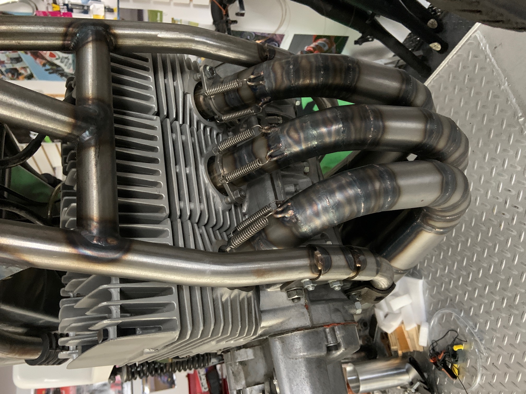
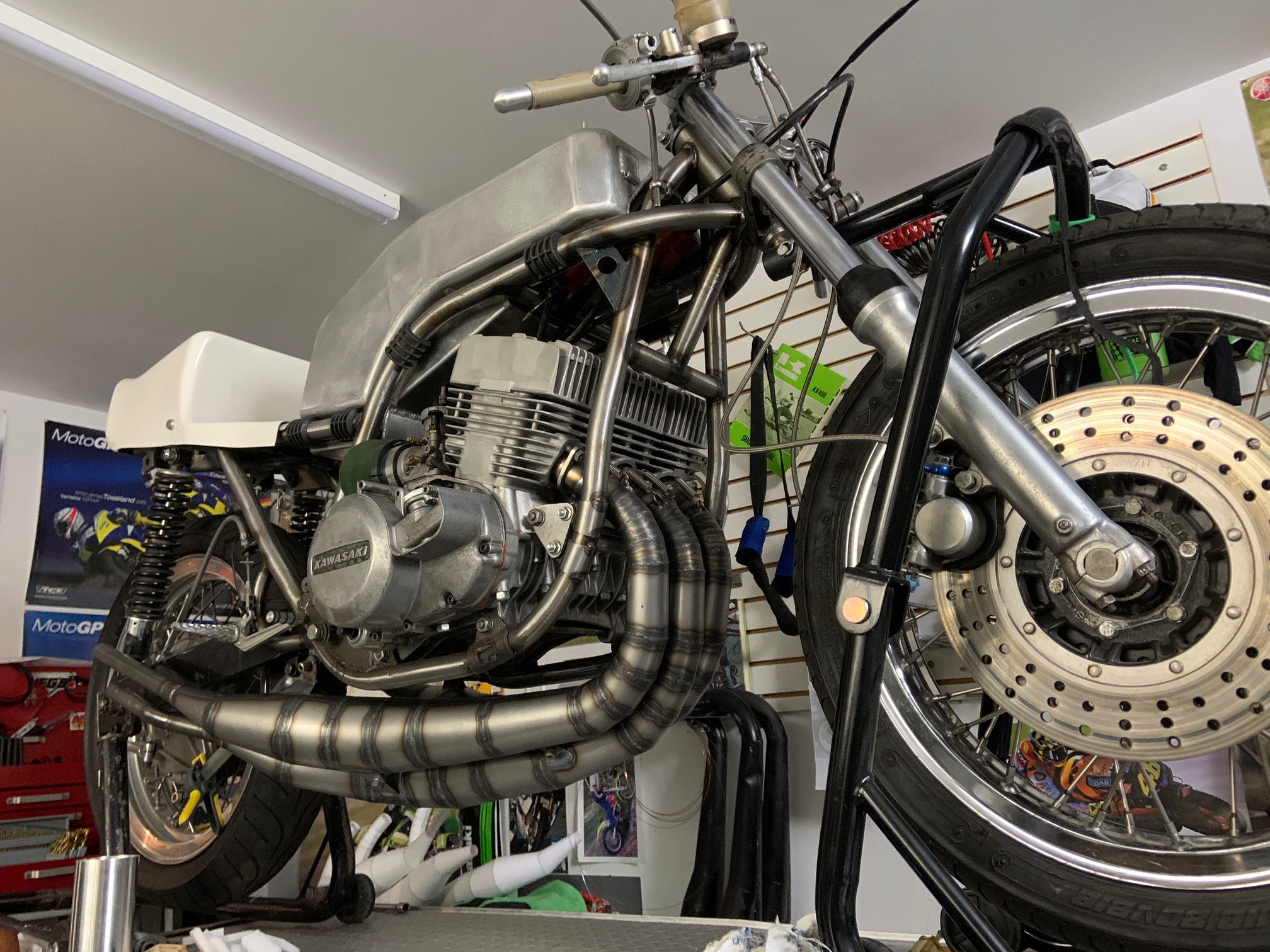
Here's an update on the fabrication of the H2r pipes. Walms had to do about four total re designs on these before we got things sorted.
The first set had 120mm bellys to try to obtain the best performance. I cut the pipes out of paper to check fitment and we had problems.
We moved on to 90mm bellys and did many fitment adjustmens along the way. Walms 3D work is outstanding and having that combined with the performance tuning software allows for a great finished result.
Photo no longer availablepipes2.JPGwas on sat02pap001files.storage.live.com
Photo no longer availablepipes1.JPGwas on sat02pap001files.storage.live.com
Photo no longer availablepipes3.JPGwas on sat02pap001files.storage.live.com
Photo no longer availablepipes4.jpgwas on sat02pap001files.storage.live.com
Photo no longer availablepipes9.jpgwas on sat02pap001files.storage.live.com
Photo no longer availablepipes11.jpgwas on sat02pap001files.storage.live.com
The final design and fitment on the pipes. They are now laser cut and rolled thanks to Mr Walms. Should start welding when the winter weather moves in.
Photo no longer availablepipes8.jpgwas on sat02pap001files.storage.live.com
Photo no longer availablepipes10.jpgwas on sat02pap001files.storage.live.com
Looking good there Jim. should have a vintage maguire quick twist throttle and some vintage coni shocks for the icing on the cake. Don’t for get the tomaselli clip ons ether.
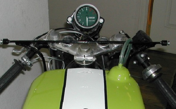
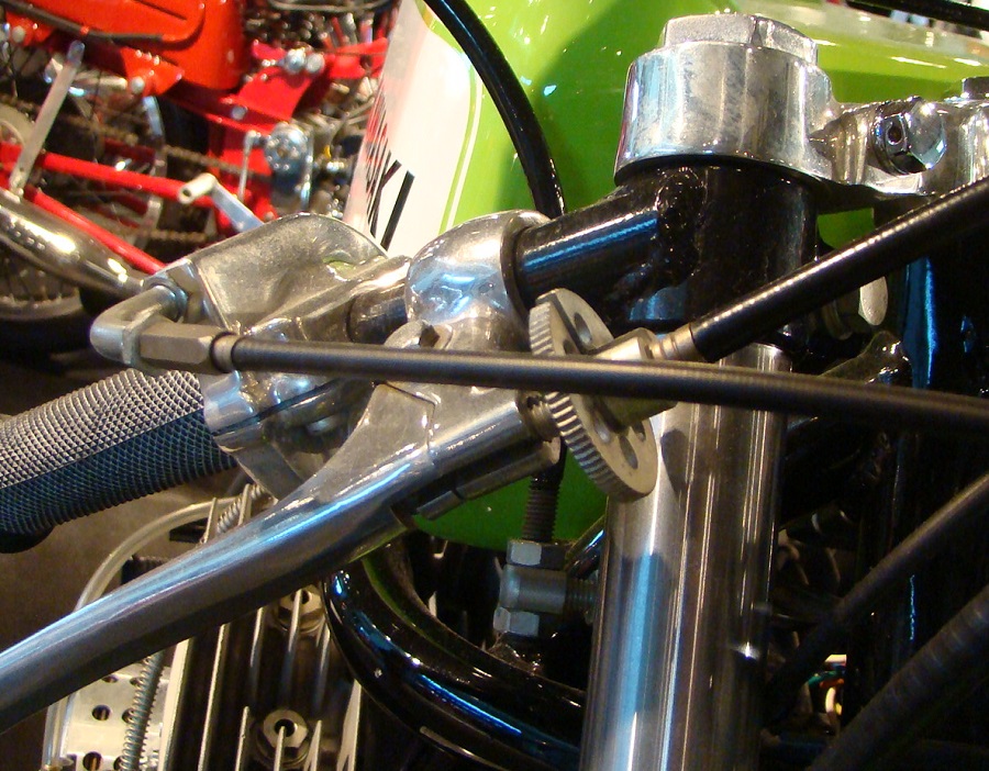
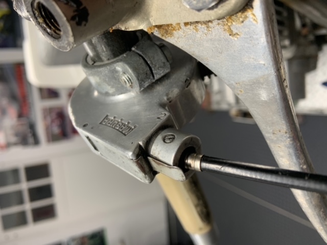
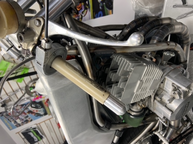
Hey Brad I have a quick throttle on it now but the cable exits 90 degrees to the left and gets in the way of the Kawasaki master cylinder. If I can find one with the cable exiting forward I’ll switch to the authentic H2r clip-ons that I have.
Oct 5, 2021 20:30:41 GMT -5autofobe said: Looking good there Jim. should have a vintage maguire quick twist throttle and some vintage coni shocks for the icing on the cake. Don’t for get the tomaselli clip ons ether.
Brad
Is this what you were talking about? Lol
Got the shocks too. As for the clip ons, I hope to use real H2r clip-ons that I have if their going to fit.
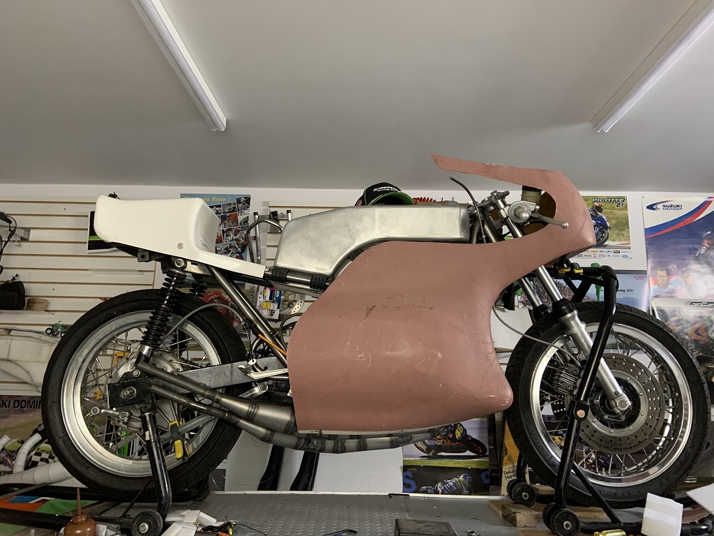
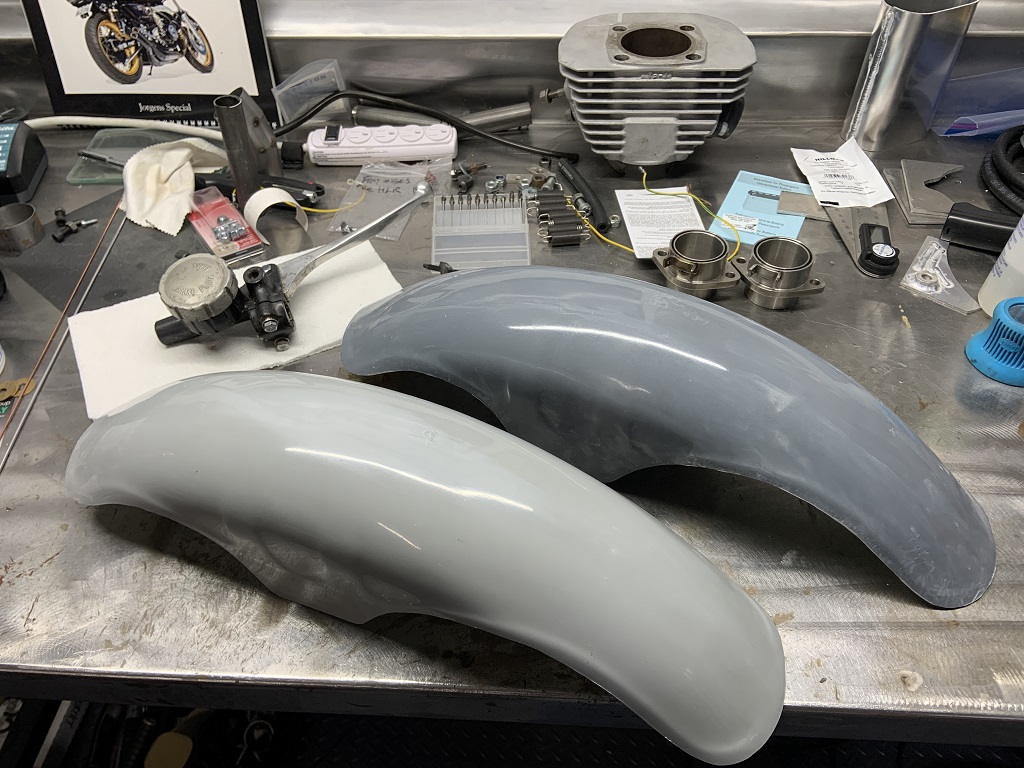
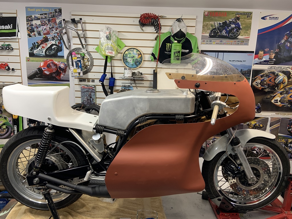
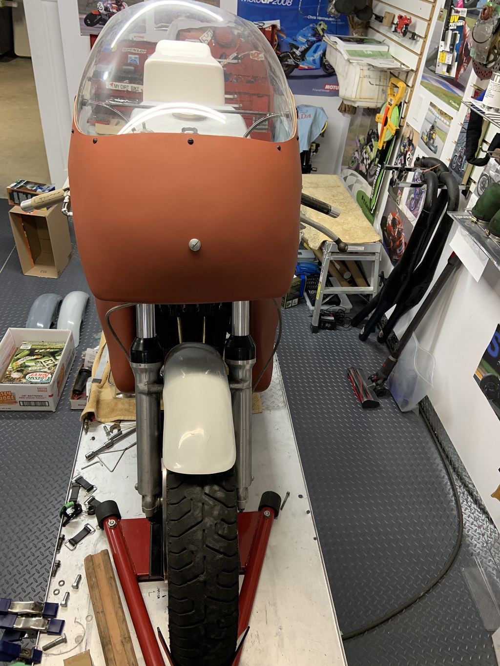
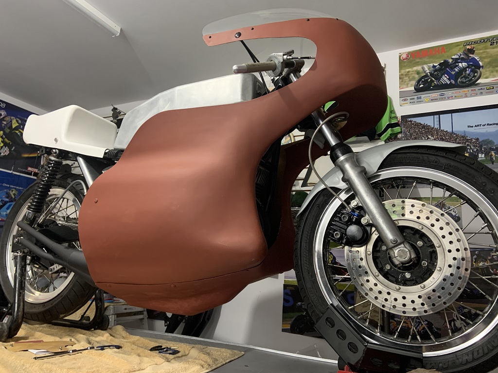
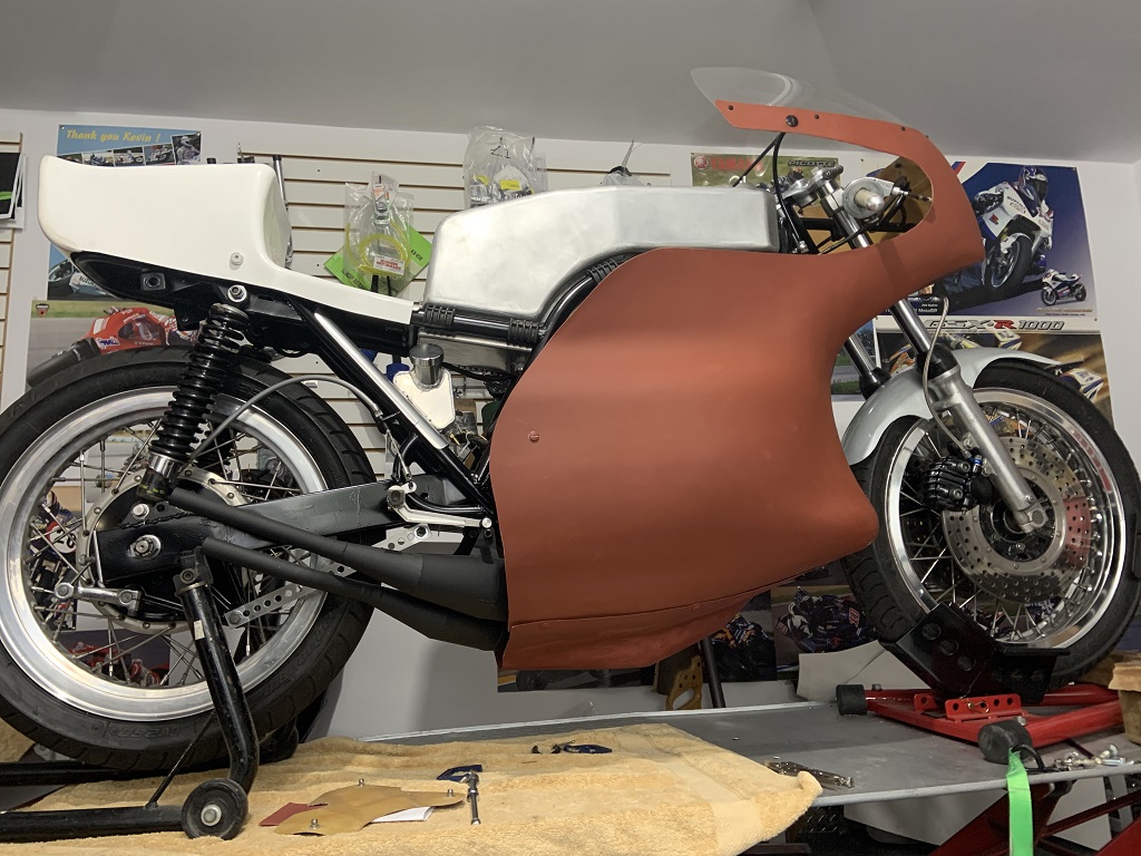
Next is getting the fairing in place, mounting the clear wind screen and fitting the front fender.
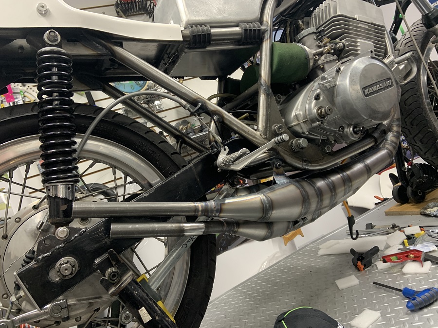
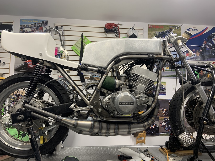
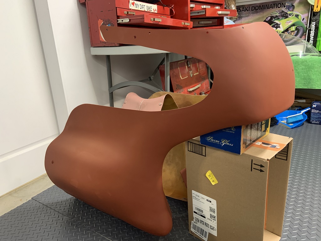
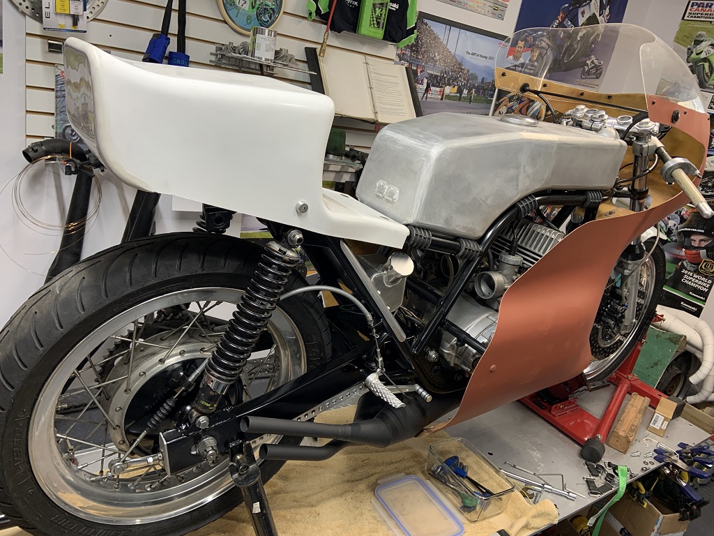
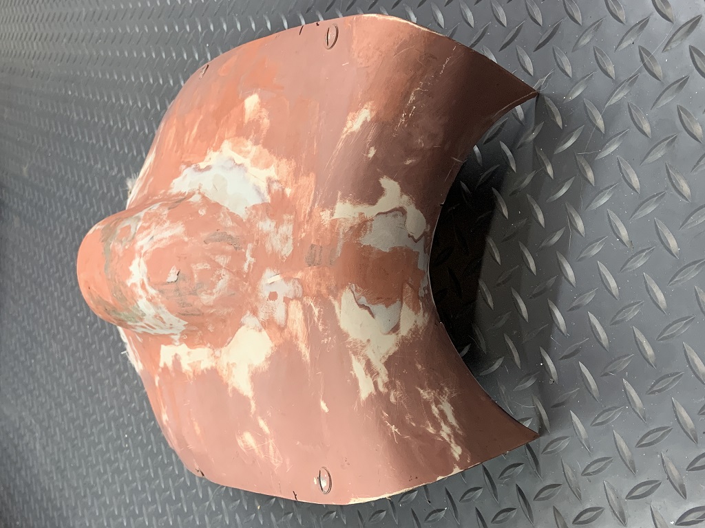
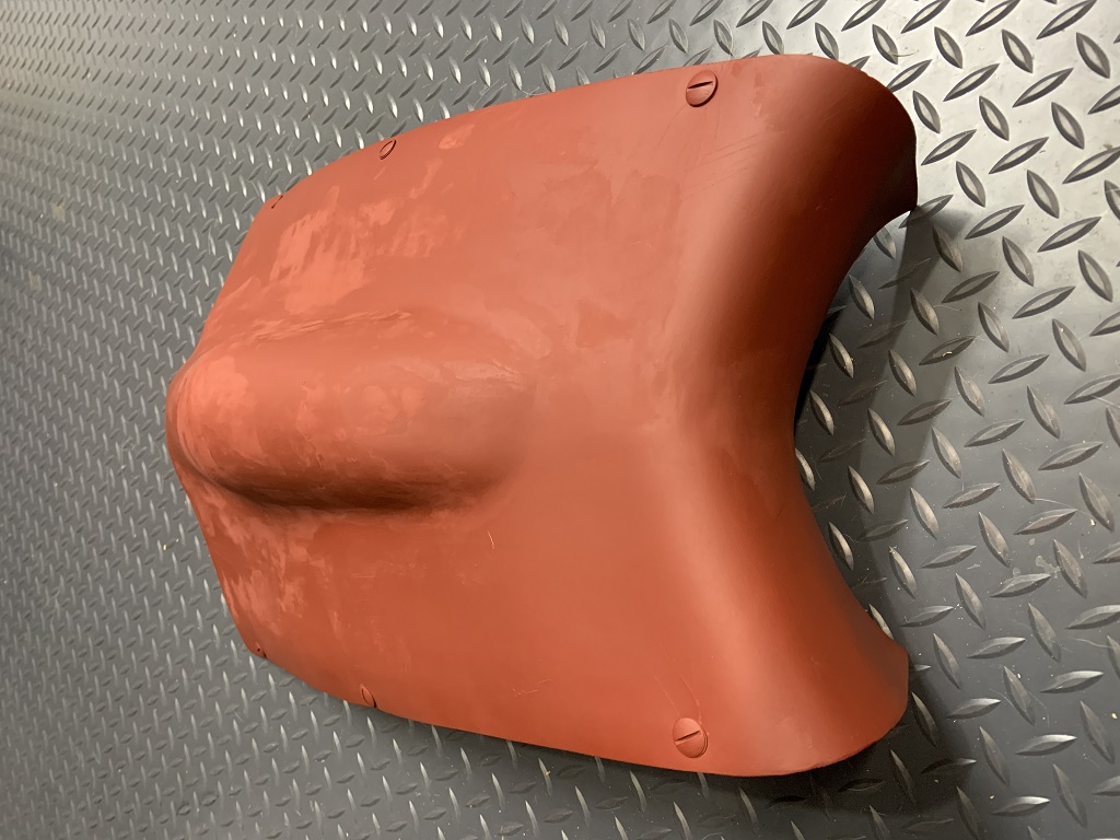
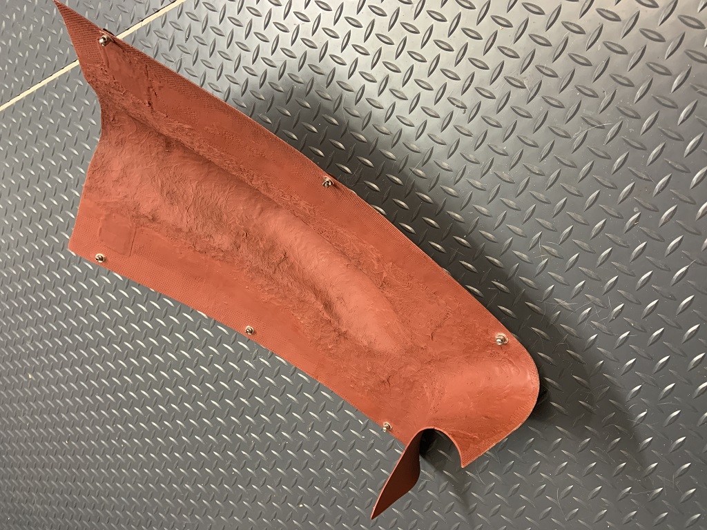
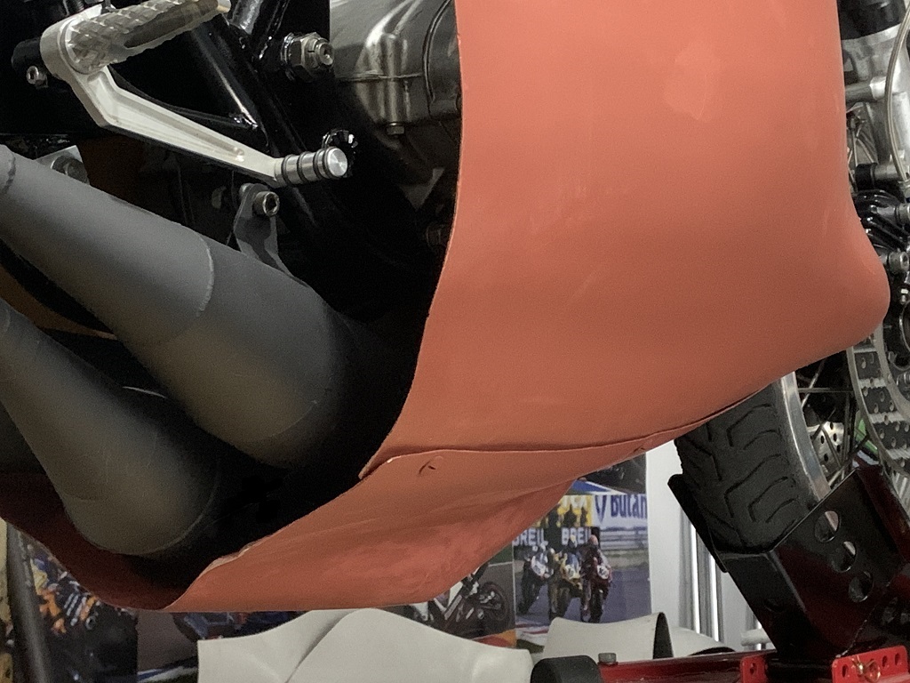
The early h2r's had all three pipes side by side with a different layout. So the flat bottom belly pan I had with the fairing would only fit with the original factory style pipes. I'm working on a new belly pan to accommodate the center pipe that is lower than the left and right pipes.
Then I should be ready for a paint job.
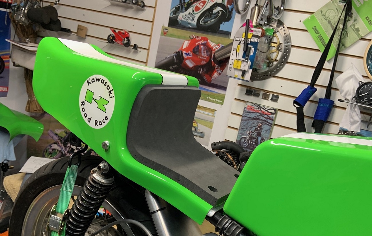
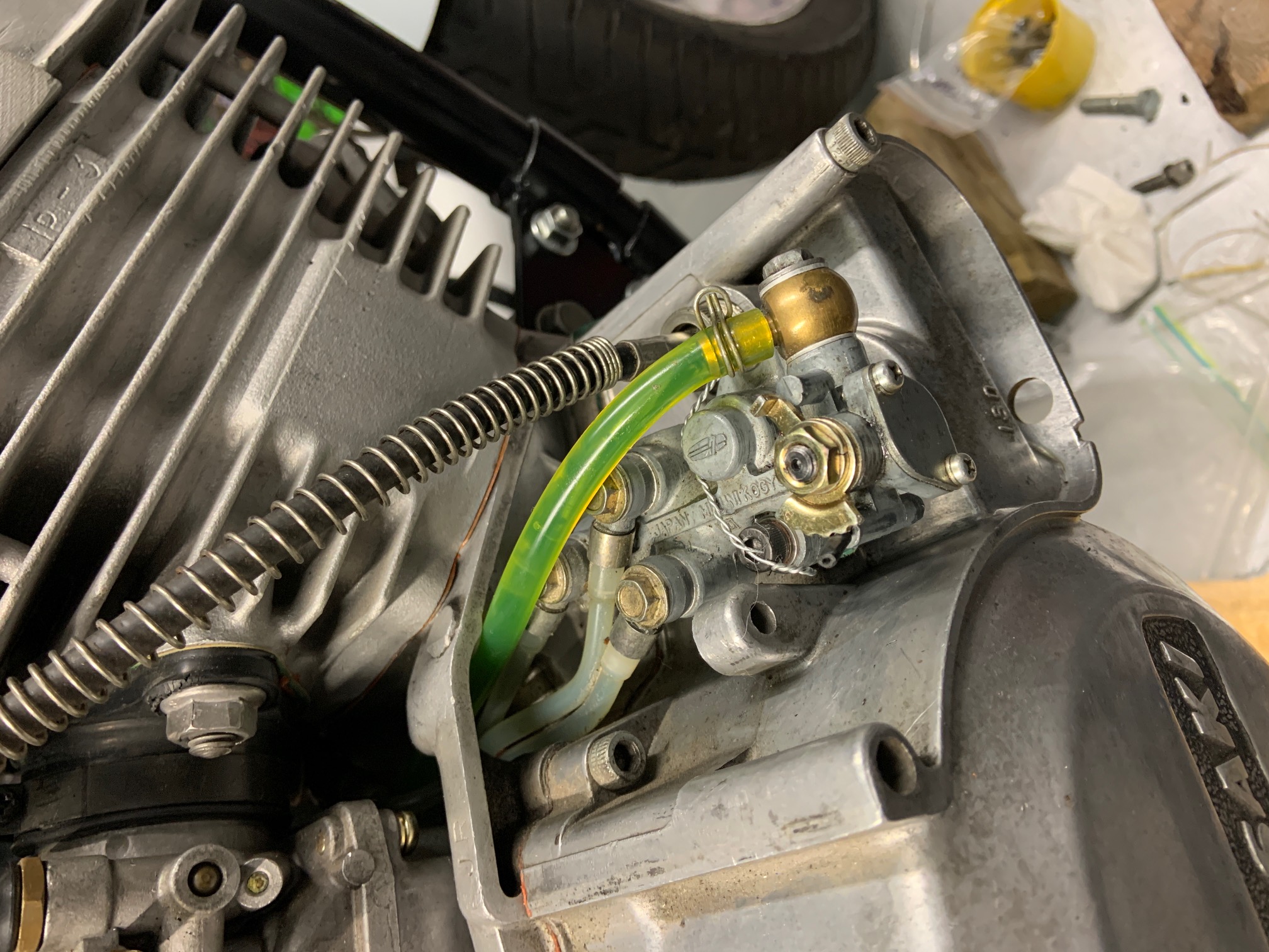
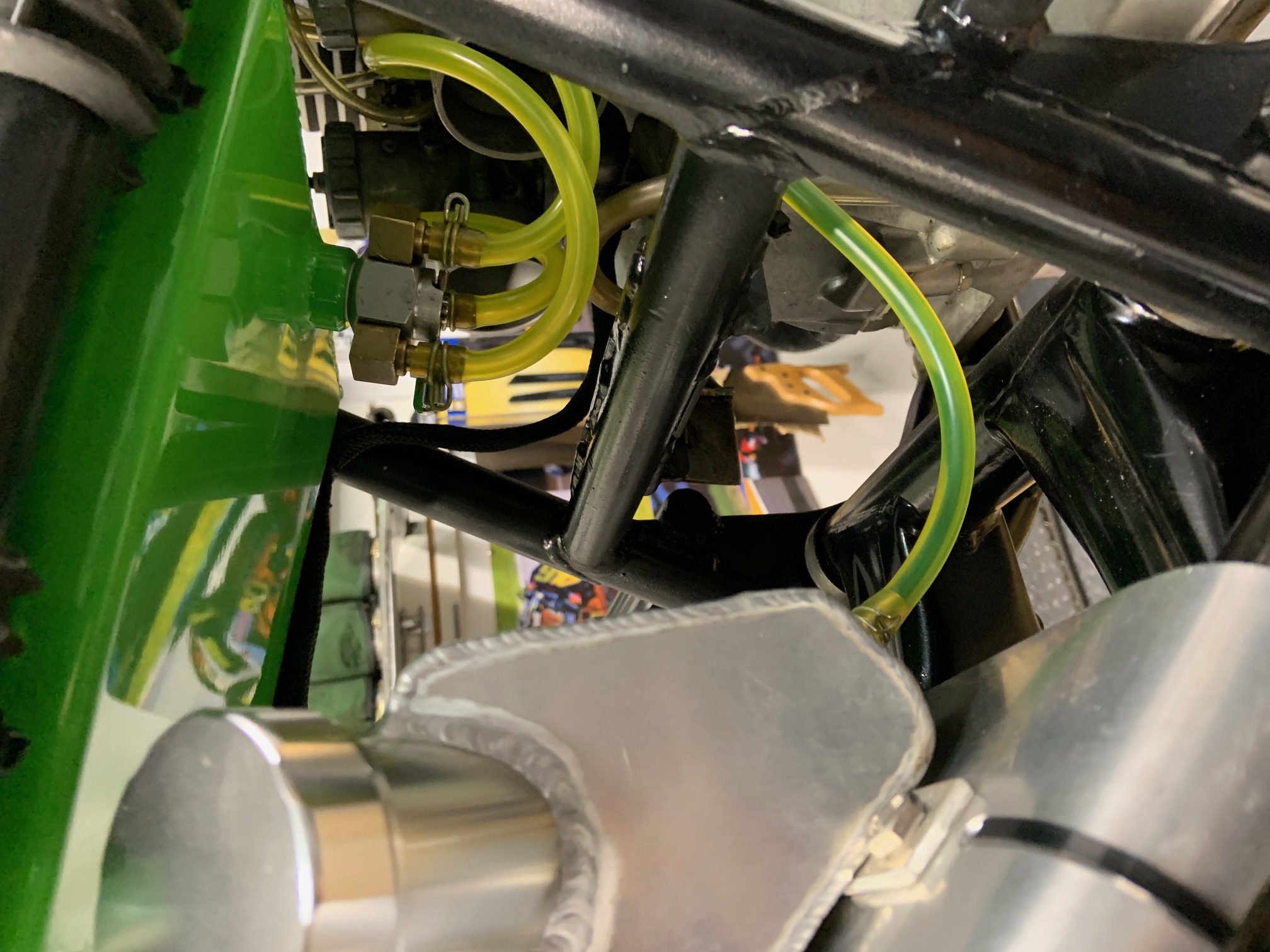
I made a rear inner fender to look like the original and as I plan to put an oil pump on it (as was on the factory h2r's) and I couldn't find a nice plastic tank like the original one so I built a small aluminum oil tank and mounted it to the rear inner fender.
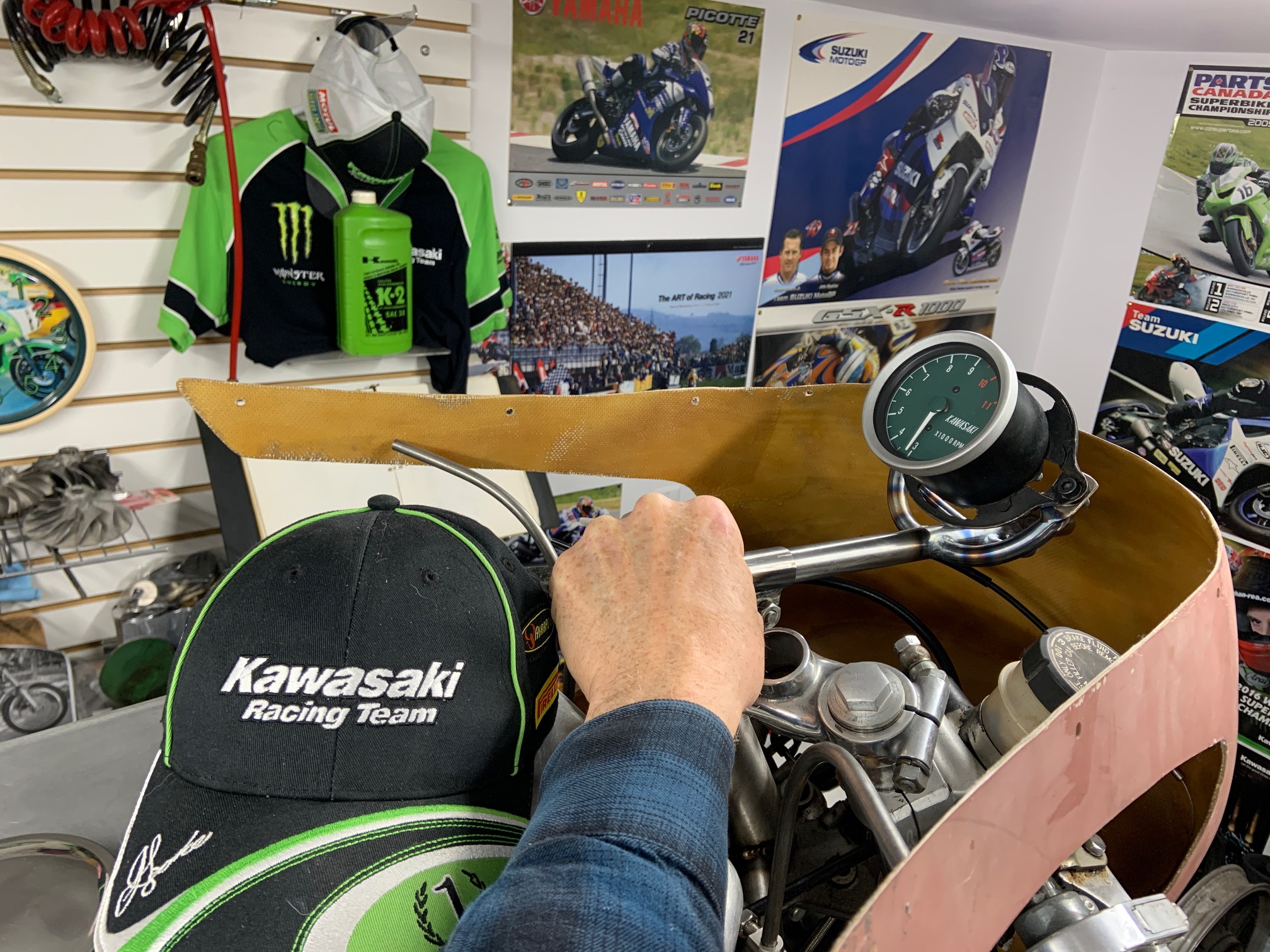
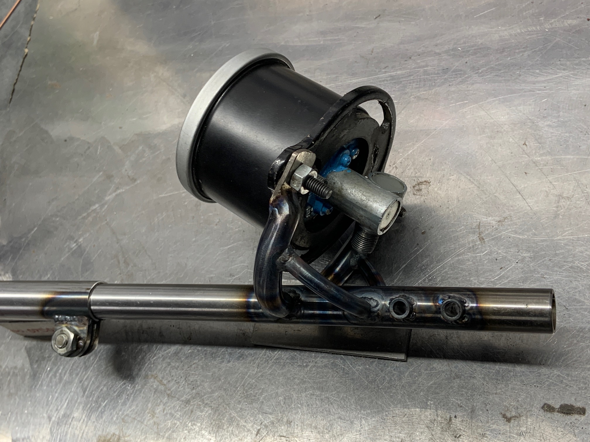
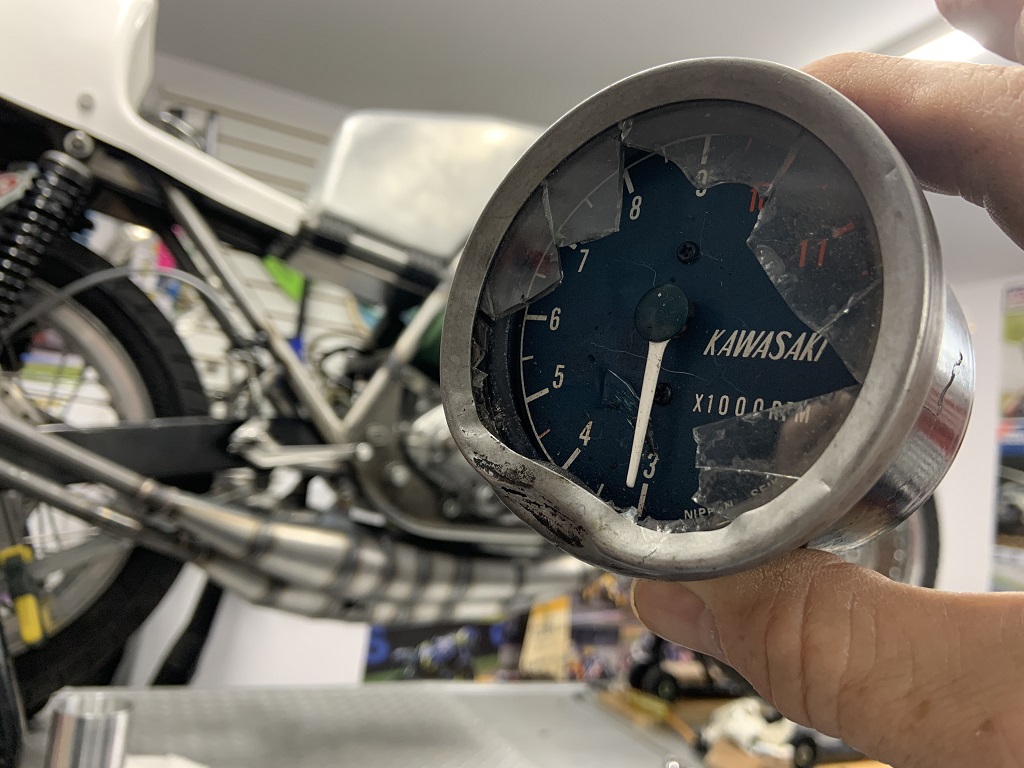
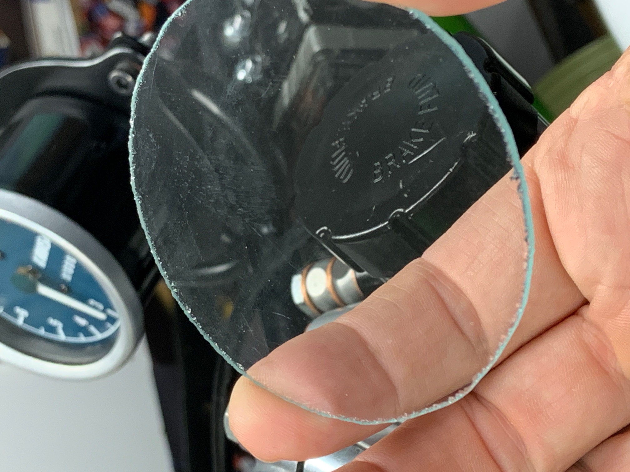
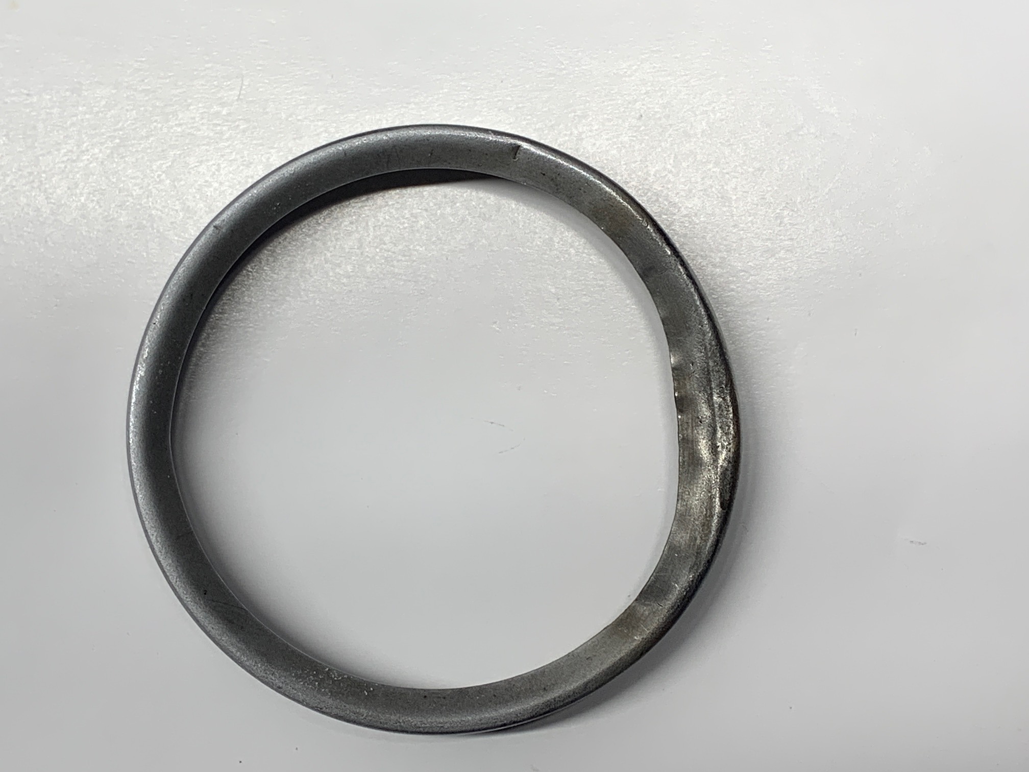
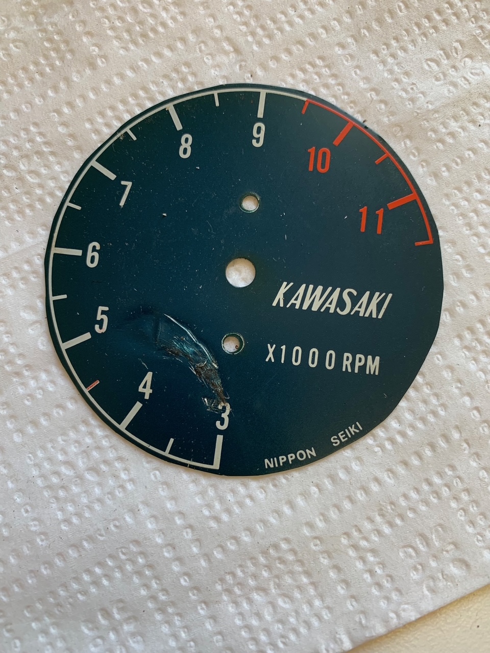
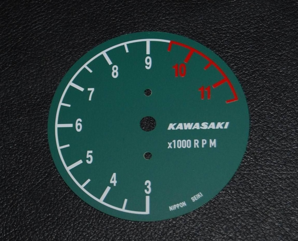
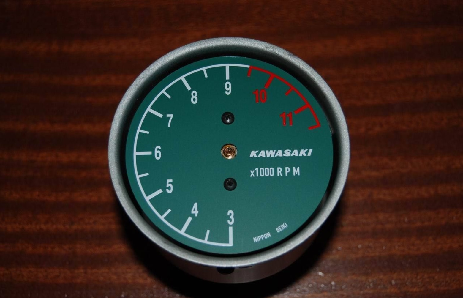
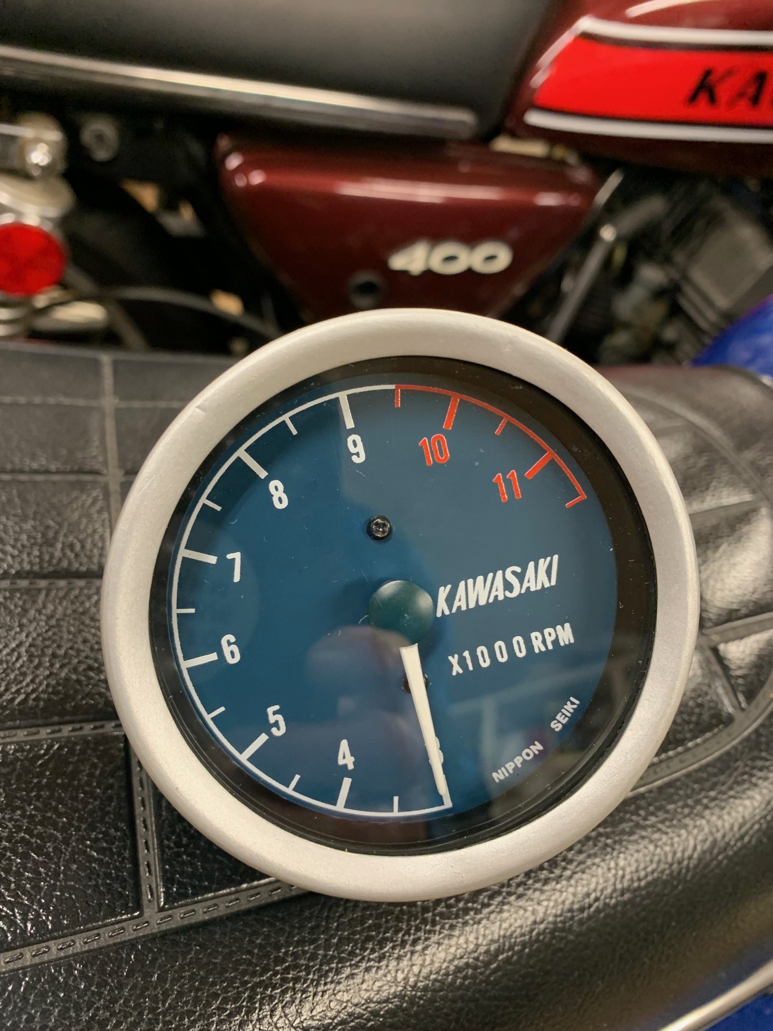
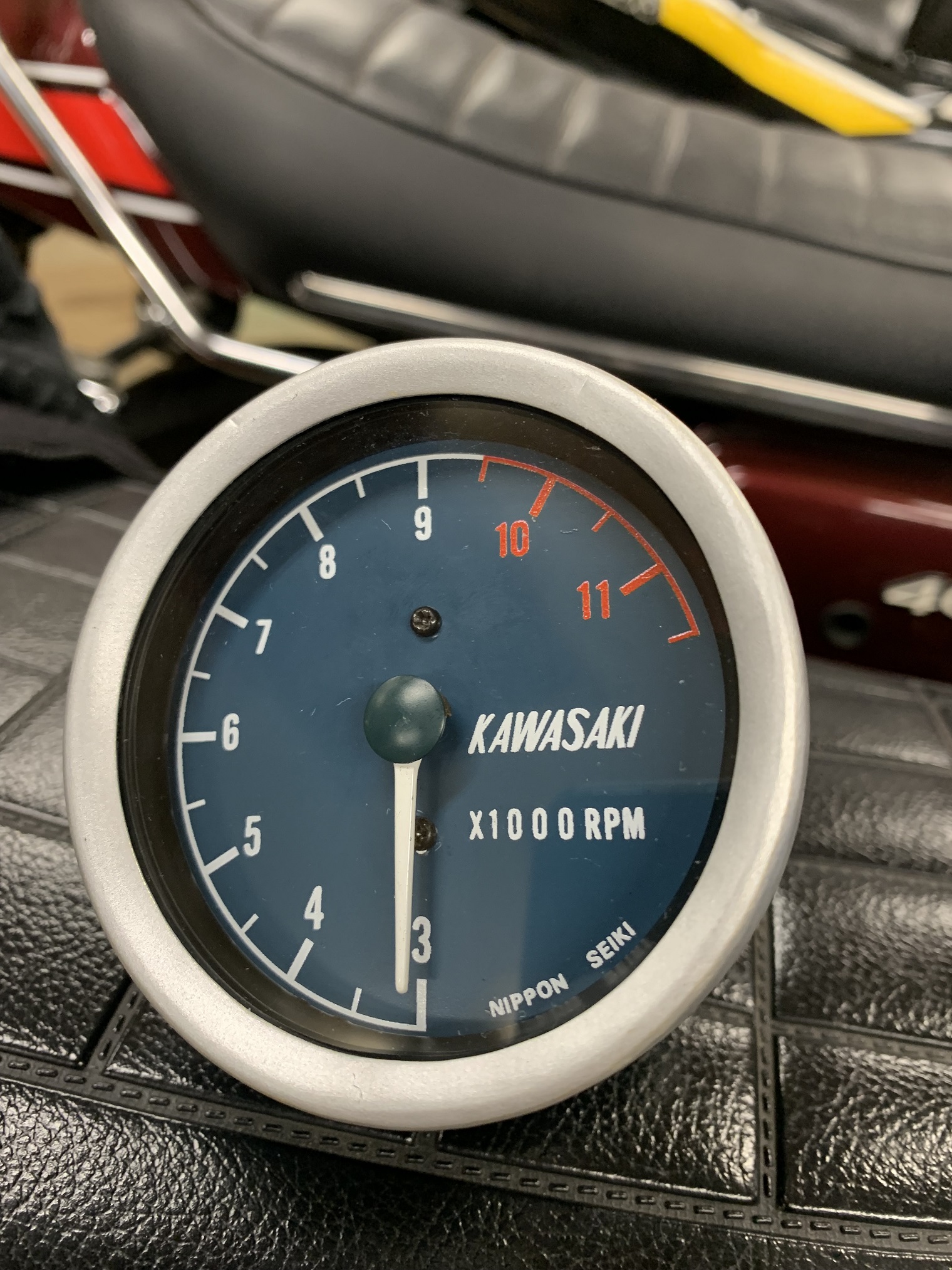
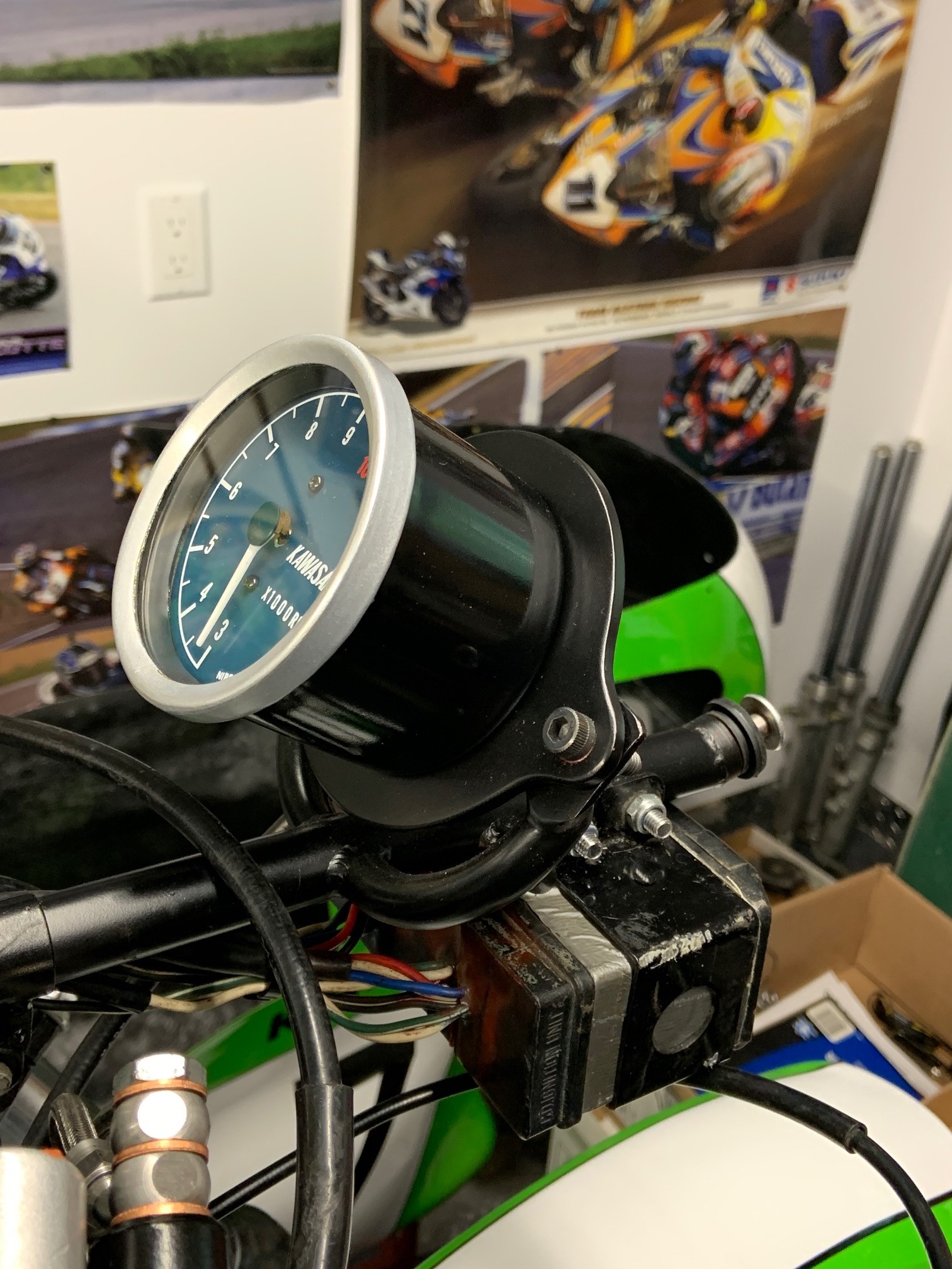
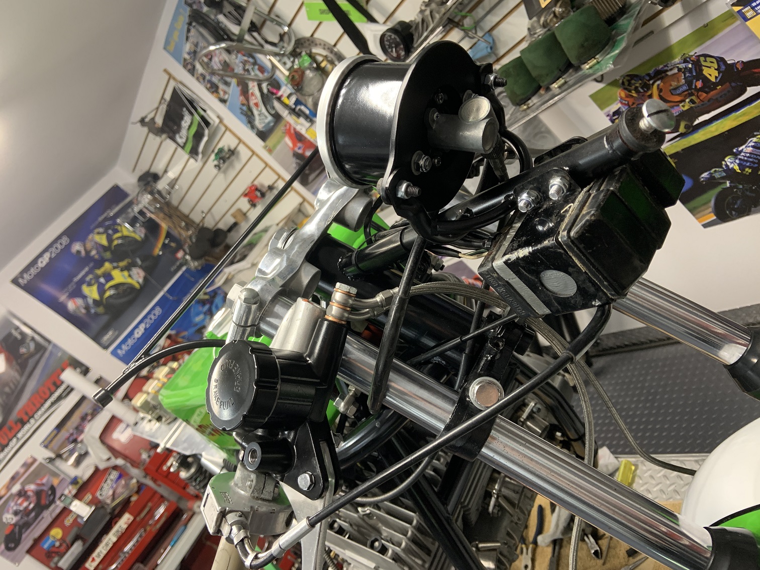
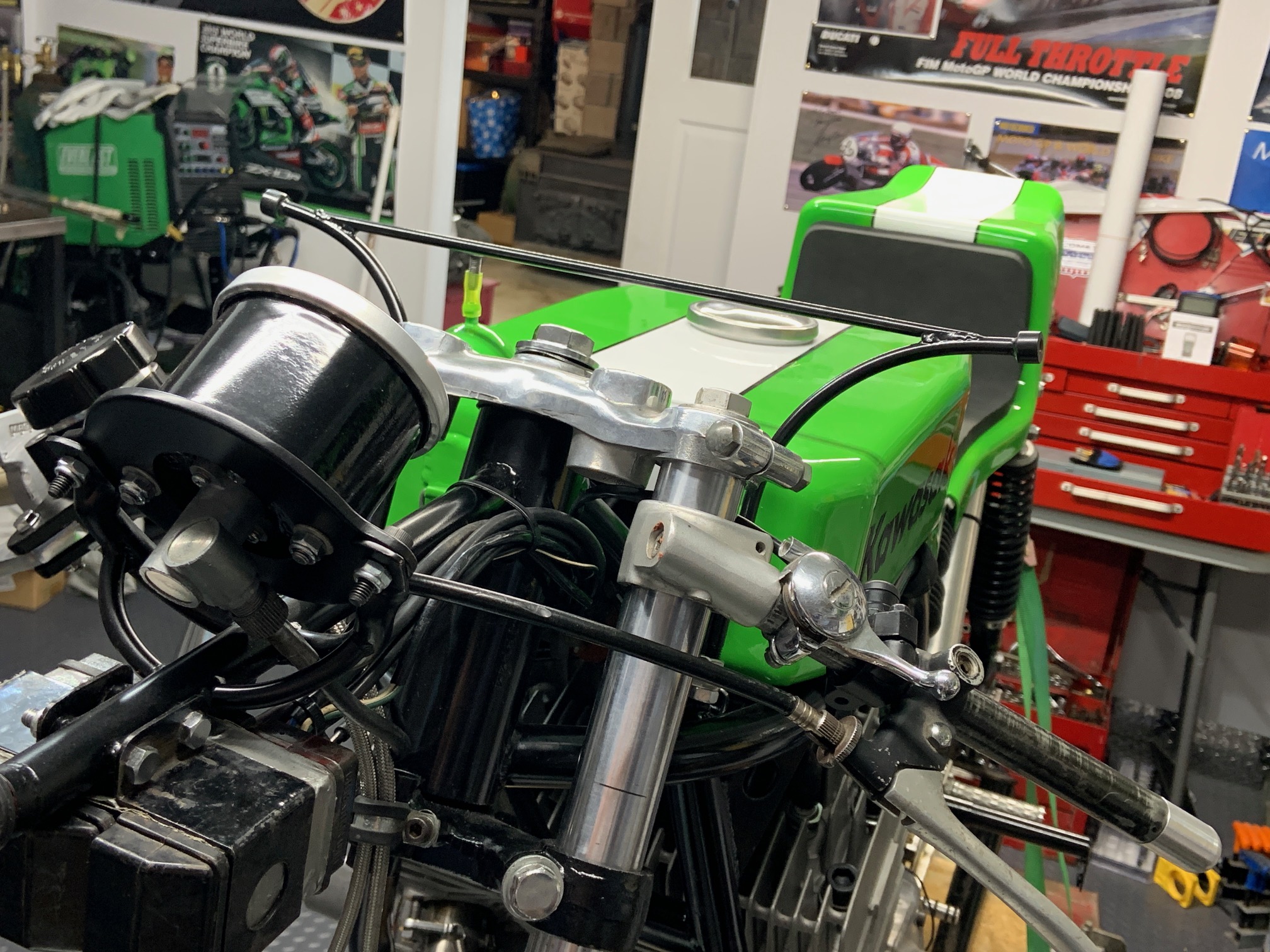
I just got an update recently on the repair of my original early h2r tachometer that was crashed.
These are not like any of the stock tachometers and none of the parts are the same. It does work and is going to be repaired. These seem to be impossible to find so I feel so lucky that one of our guys here on the board has a lot of experience with instrument reconditioning and were hoping to get it fixed up and looking good so I can use it on the project.
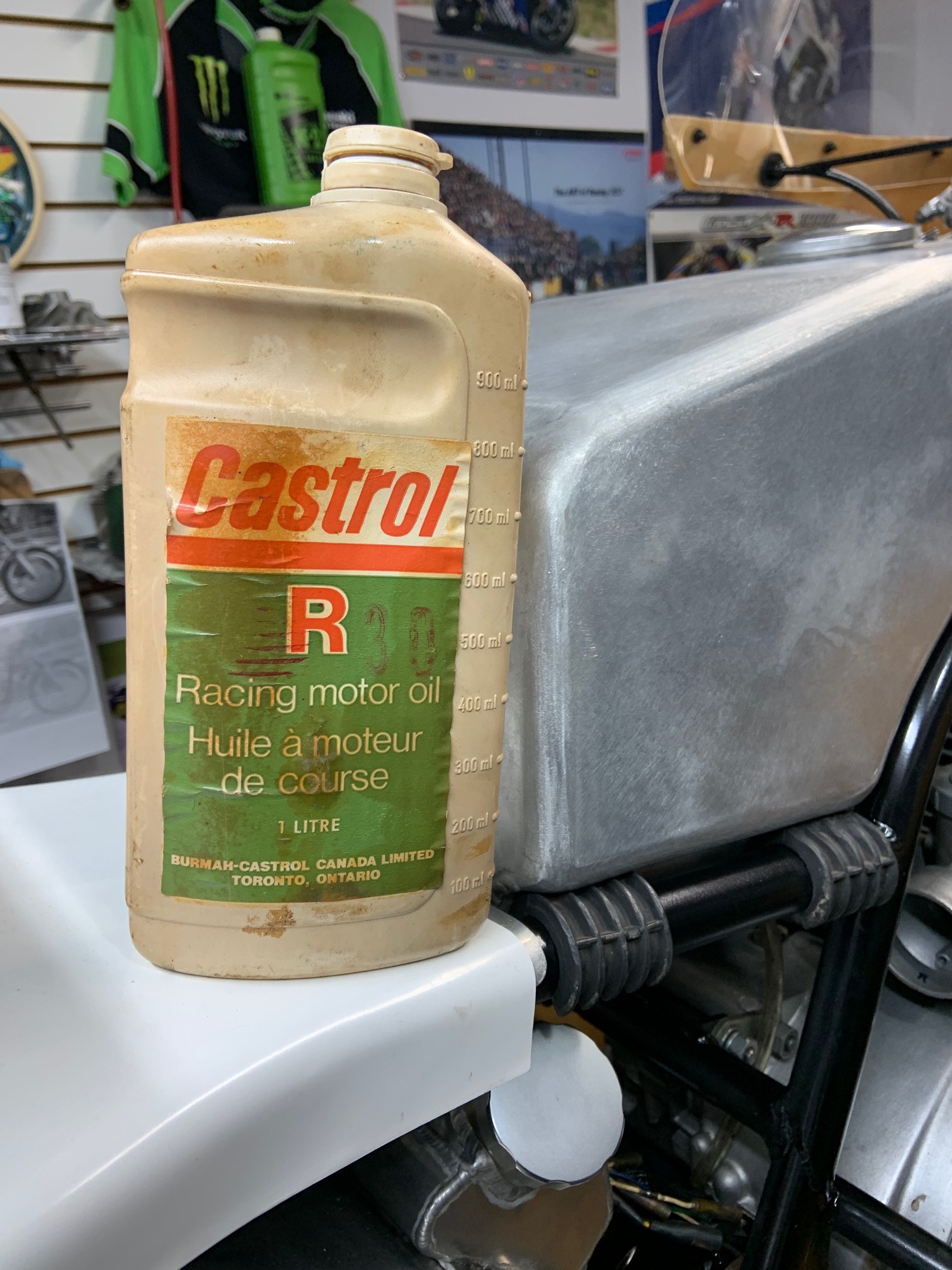
What a project - the build is only part of the story.. it's like opening a old "history of Kawasaki racing" book .. and every page smells like Castrol Racing oil.
Nov 15, 2022 7:15:47 GMT -5zambia said: What a project - the build is only part of the story.. it's like opening a old "history of Kawasaki racing" book .. and every page smells like Castrol Racing oil.
I mixed a batch for the start-up on the other bike at Mosport this summer Ian.
insert code hereIt’s coming along great Jim. I don’t the people realize how much time it takes to make and fit all the parts. It takes forever just to mount the fairing in the right place and make it look correct. It takes a special person to pull it all off. It must feel good to be getting near the end.
Thanks for all the compliments. Here`s some further updates.
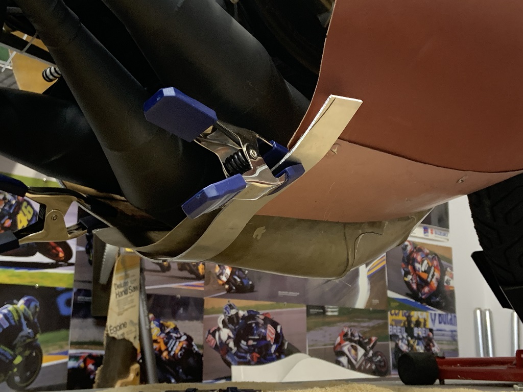
As you can see in the picture below the pipes are slightly lower than the fairing.
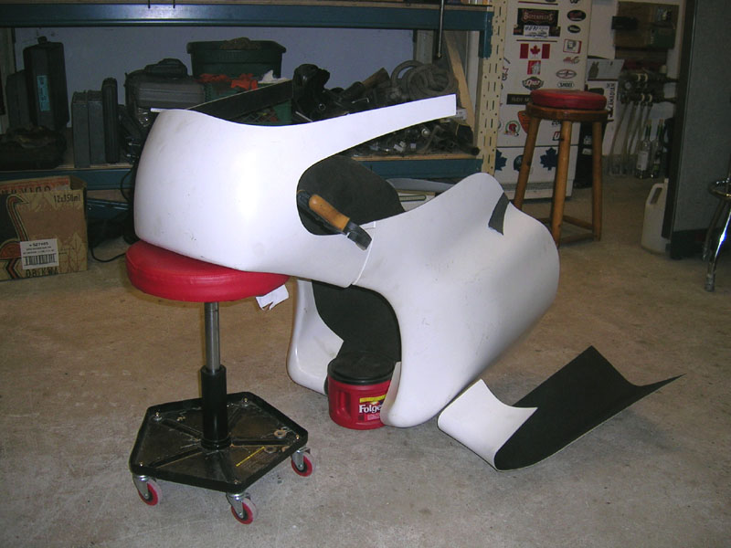
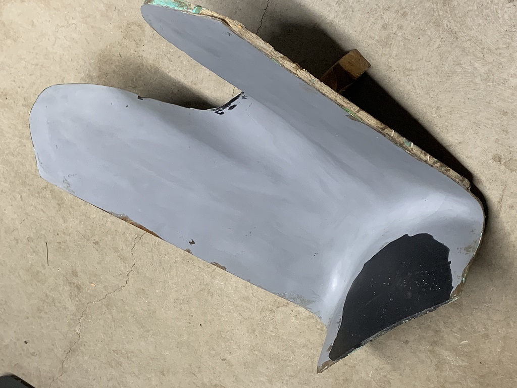
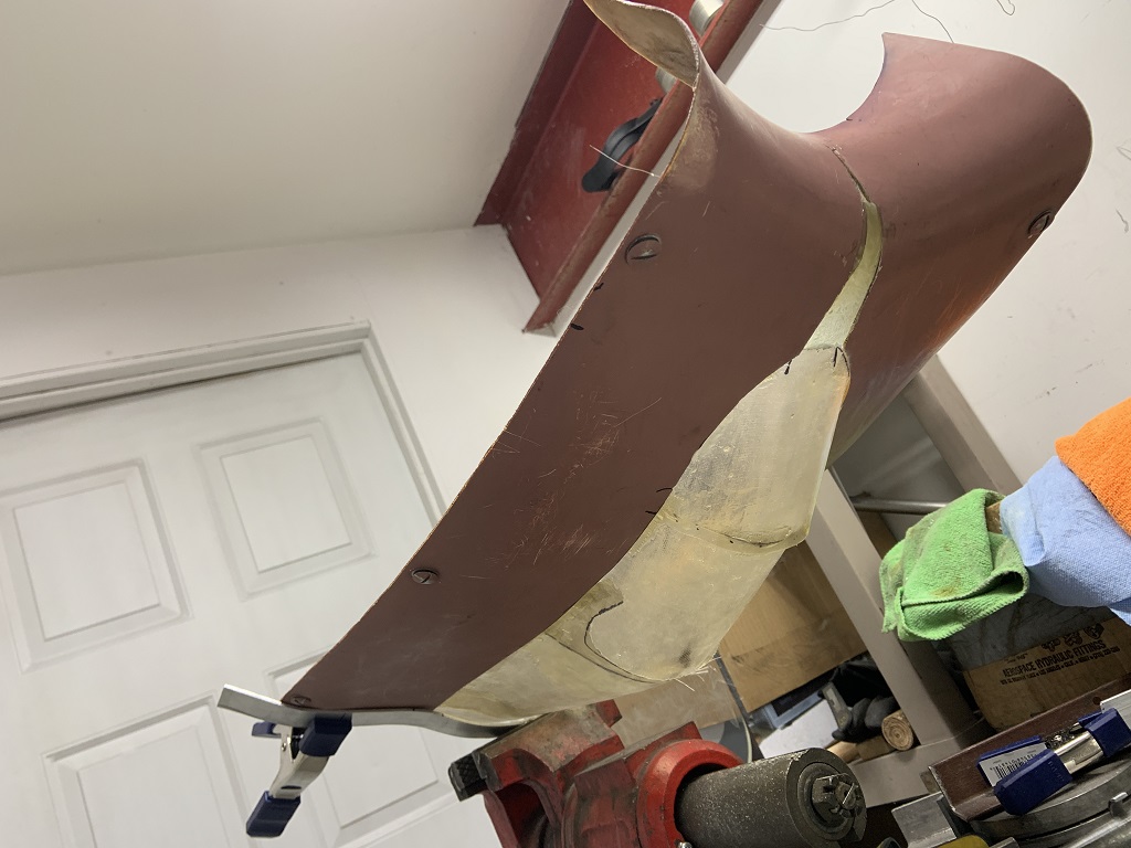
This meant that the original belly pan would not fit. To create some space for the pipes I had to modify the belly pan. I`m not a fiberglass guy. So it turned out that it was a lot more difficult than I figured.
I cut the original pan open down the center to allow the center pipe to be exposed but there was no support for the sides of the fairing like that.
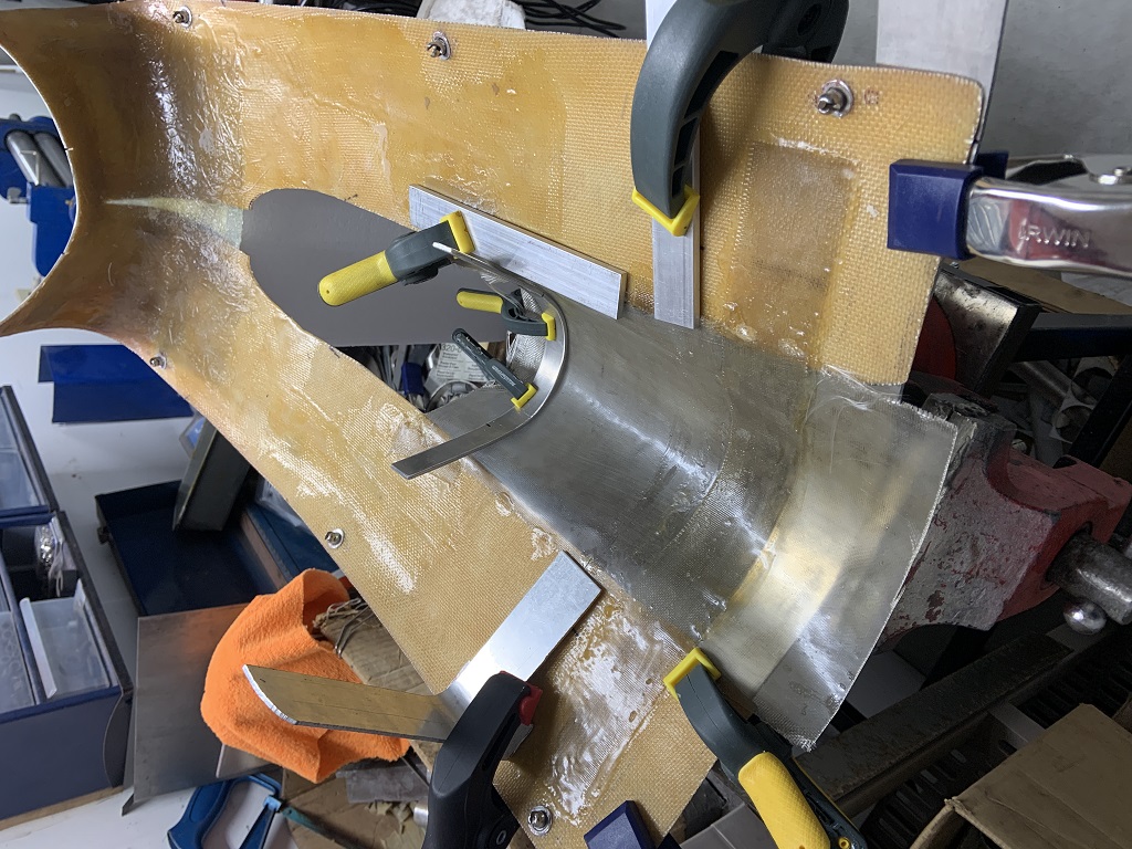
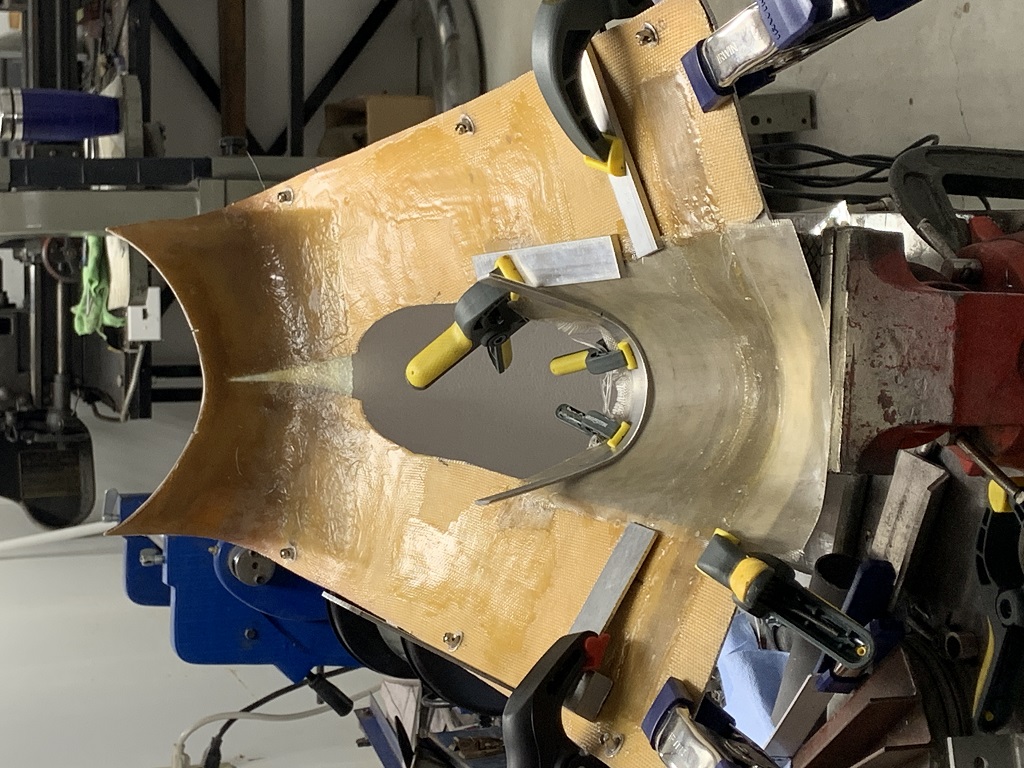
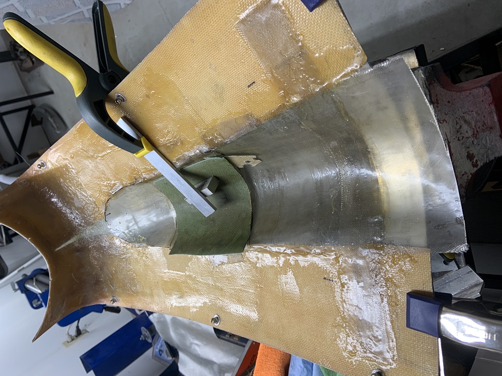
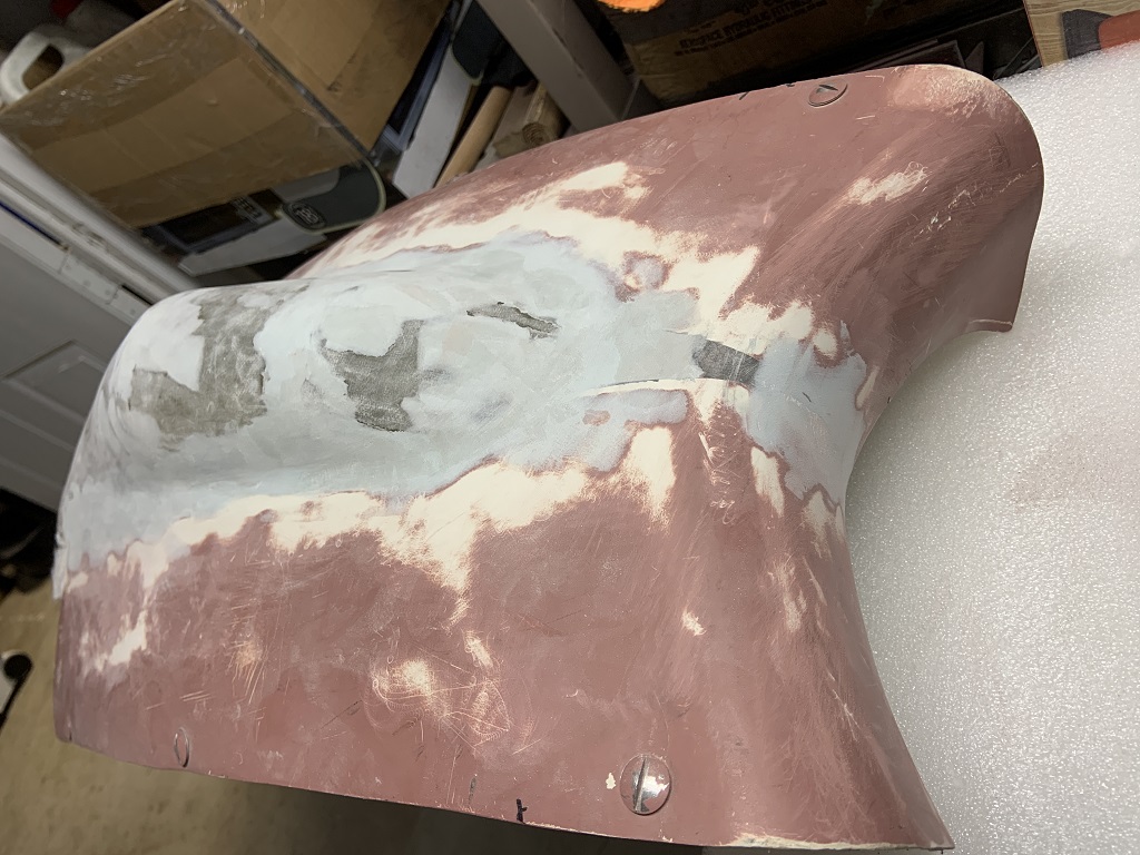
I then had to fiberglass the front area where it was slit open while making sure it still lined up with the fairing.
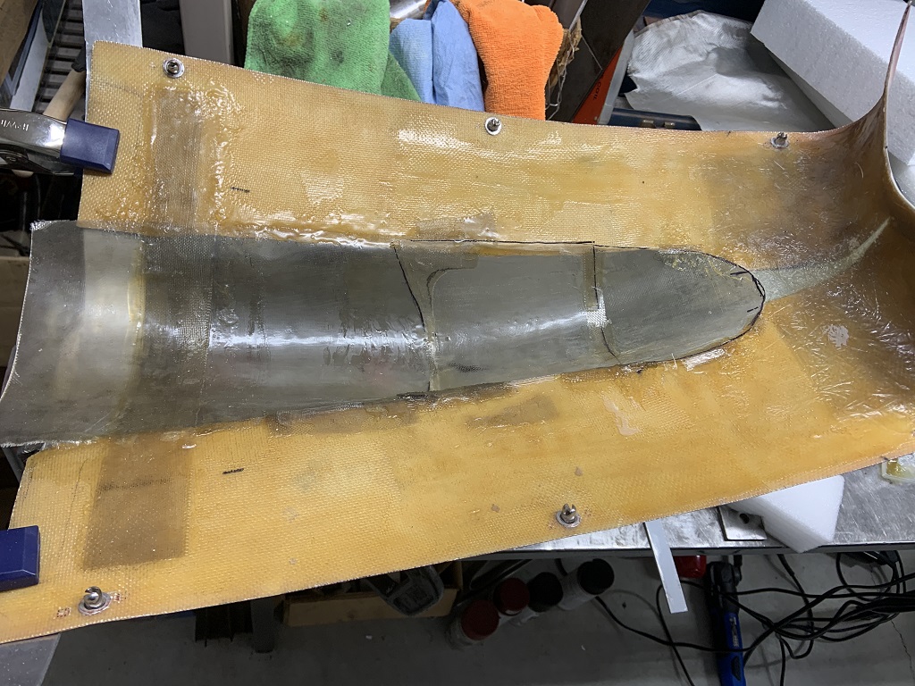
I decided to form a fiberglass piece using one of the molds I had to allow clearance for the center pipe and try to fit it in. You can see that this mold has a center section to allow for a low pipe.
I made a small piece from the center section of the mold and it didn't quite fit so I made a couple more and joined them together. It was messy difficult job and I didn`t like the look but it seemed to work.
Custom builds are always a pain in the ass.I had the same problem with mine but chose to move the pipes up To keep it inside the original fairing. Your solution turned out pretty good. I guess that’s why they used the skinny pipes originally.Less hanging out in the air stream. Brad
I think I would only do what has to be done to get a job done but that’s the limit. I had a real fiberglass guy make the front fender. Just lucky I had the mold.
It takes quite a lot of skill and effort to do it right and it’s all smelly dusty and messy as far as I’m concerned. Lol.
Have a look at www.rayplex.ca . There’s some good how to videos there.
Holy smokes, just reread the whole thread! Its amazing how fast 10yrs went by, though probably not for you eh Jim. 😉 The bike looks fantastic, but the wait was agonizing.....
I have been following this thread for quite a while,I just saw the paint is done. I am restoring an old H2, made into a racer. What green paint did you use? I am now looking for paint. Thanks Albert
Again guys I have to thank you for all the compliments. It helps keep me motivated to get back at the work to do.
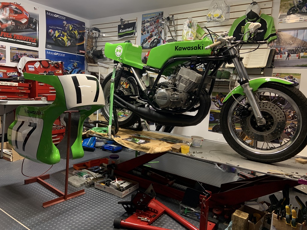
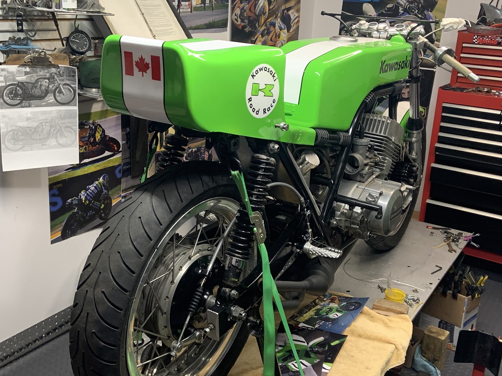
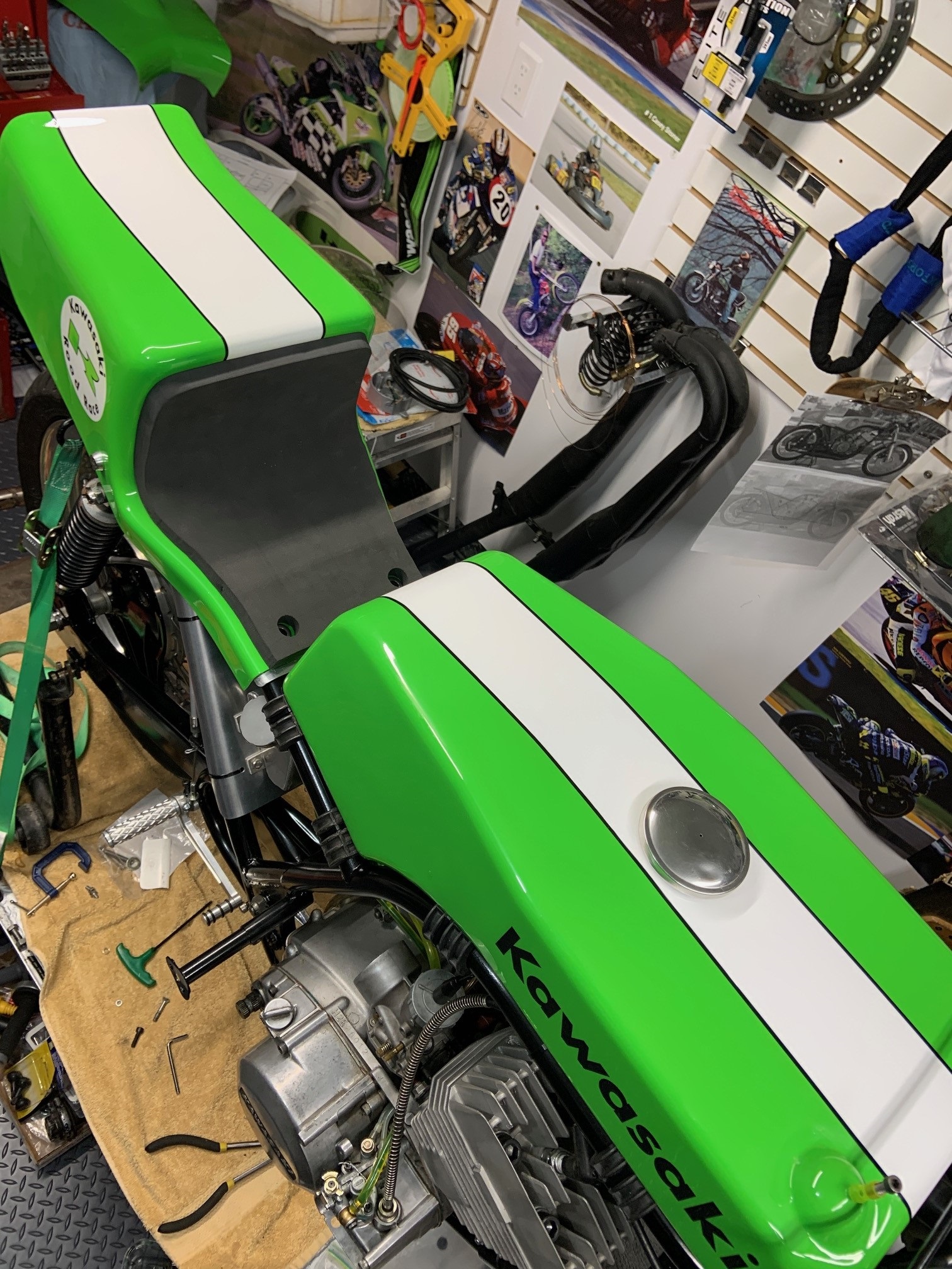
The paint color was a big problem.
ColorRite supplies Kawasaki paint from the USA. I was told to use Color-Rite code 617. The price for a sample can shipped to Canada was over the moon so I scrapped that test.
I tried a paint scan of some Kawasaki advertising artwork that seemed to have the correct green. The local paint supplier scanned it and I bought a can. It wasn't even close.
Then I picked up a rattle-can of Dupli-Color green Engine Enamel. It was great but it was a better match for the modern green they use on the new dirt bikes you see at the dealer. The old H2r's had a deeper green shade.
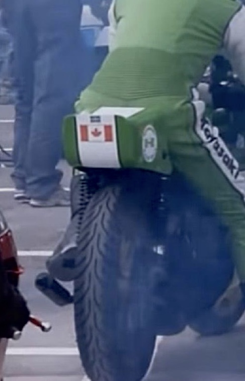
Then I took some photo's to John Connery in Toronto (Scarborough). His brother painted the race bikes back in the 70's and he just did a friends H1r. He puled out a can, mixed it up and it looked perfect. So John Connery got to do the paint and I think the color is good. (He painted in the Canadian flag for me) Andre at Diablo has the round decal's and he gave me the black "Kawasaki" decals from a 70's dirt bike and they fit perfectly.
Sorry I cant help you with a match code but I would have been pissed if it was the wrong green.
Beauty job Jimmy! Like the shop too. This thread is almost 10 years old. We'll see it again at Mosport this year I reckon. I trust you'll piss off the pit dogs revving the hell out of it like last year.
May 23, 2023 14:56:24 GMT -5givr said: Beauty job Jimmy! Like the shop too. This thread is almost 10 years old. We'll see it again at Mosport this year I reckon. I trust you'll piss off the pit dogs revving the hell out of it like last year.
Good to see that you're still alive Anthony.... Give me a call if you ever come back to Fairlane Lake.
Still alive, grumpy as hell lately, but living. Getting as old as you guys... 🙂 I'll be up at Farlain Lake the weekend of June 2nd. Band weekend jam session and epic BBQ. Noise complaints to ensue. A little off topic from Jimmy's thread but what the heck happened to B9HS spark plugs? Discontinued from NGK's website I read. Autolite 2634's are the answer then eh?
Always good to hear from you Givr. Yes, hoping to bring the H2r and the KR750 to VRRA Mosport this year. Dave Crussell is coming from California hopefully to race his H2r. Tommy Canellos is running his Big Horn 350 also. Should be an epic Kawasaki weekend.
Walms has a camper so I hope he is there to help with the famous Giver Mosport BBQ feast.
Maybe we can convince Dave to come with the new new custom triple he’s building. It’s almost finished and we want to see it.
Autolites are great Anthony. I have had much better luck with them than with the NGKs. They last a whole season without ever fouling. I get them online from the Wrench Monkey. They're a little hard to find elsewhere.
And , Jim, it may happen with the new bike but I really need to sort out this H1B and get it sold. Cash is king... There's a swap meet this weekend here and I think all that I need is to get the clip position right to make it run perfect. But then , it is me doing the tuning.....
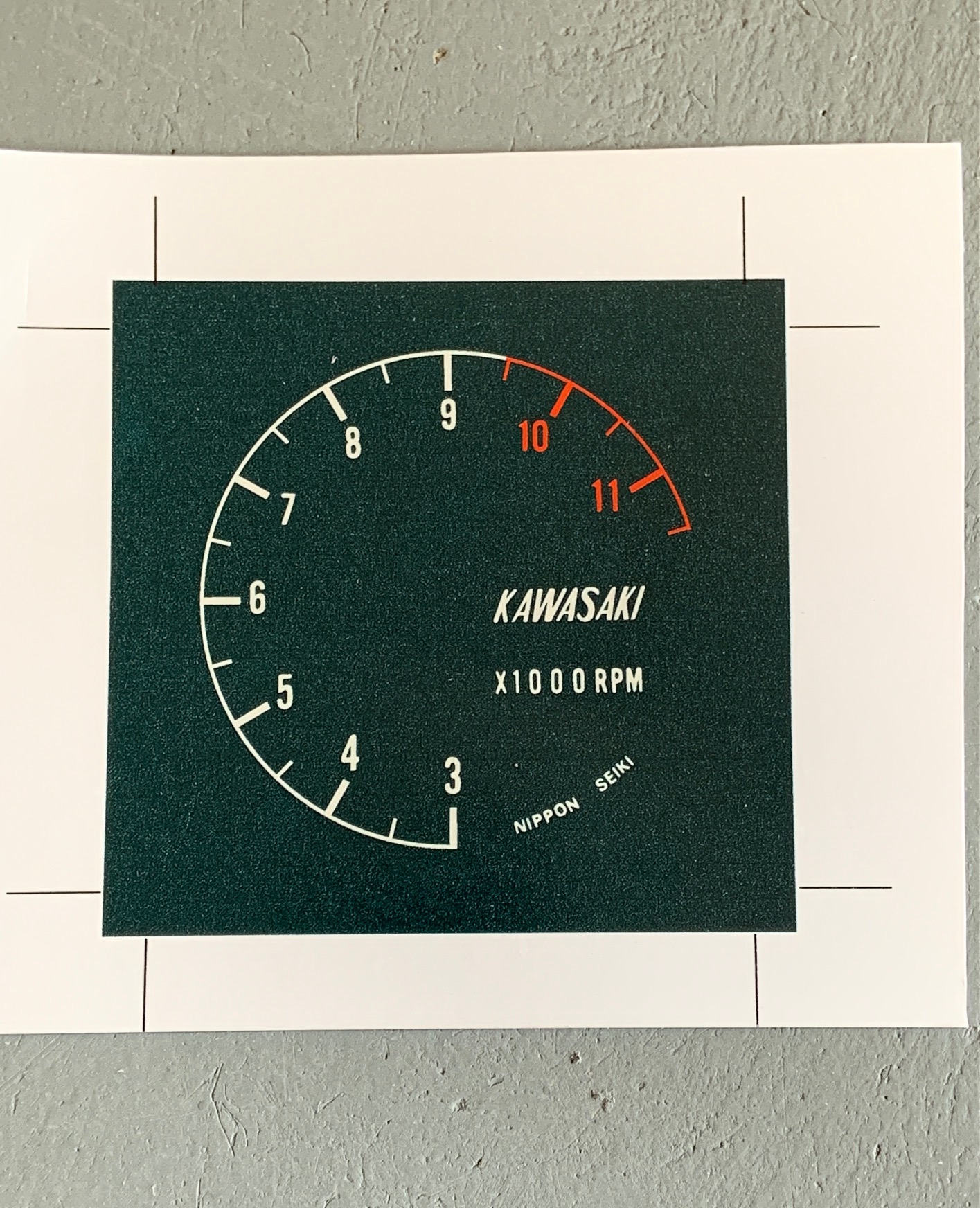
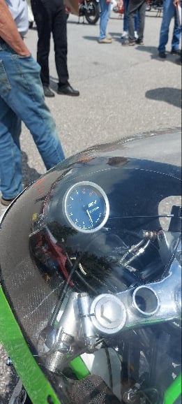
I now have an update on the repair of my original early h2r tachometer that was crashed.
As I mentioned previously,these are not like any of the stock tachometers and none of the parts are the same. They are impossible to find so I feel so lucky that I had this smashed one and Zambia took a shot at the repair.
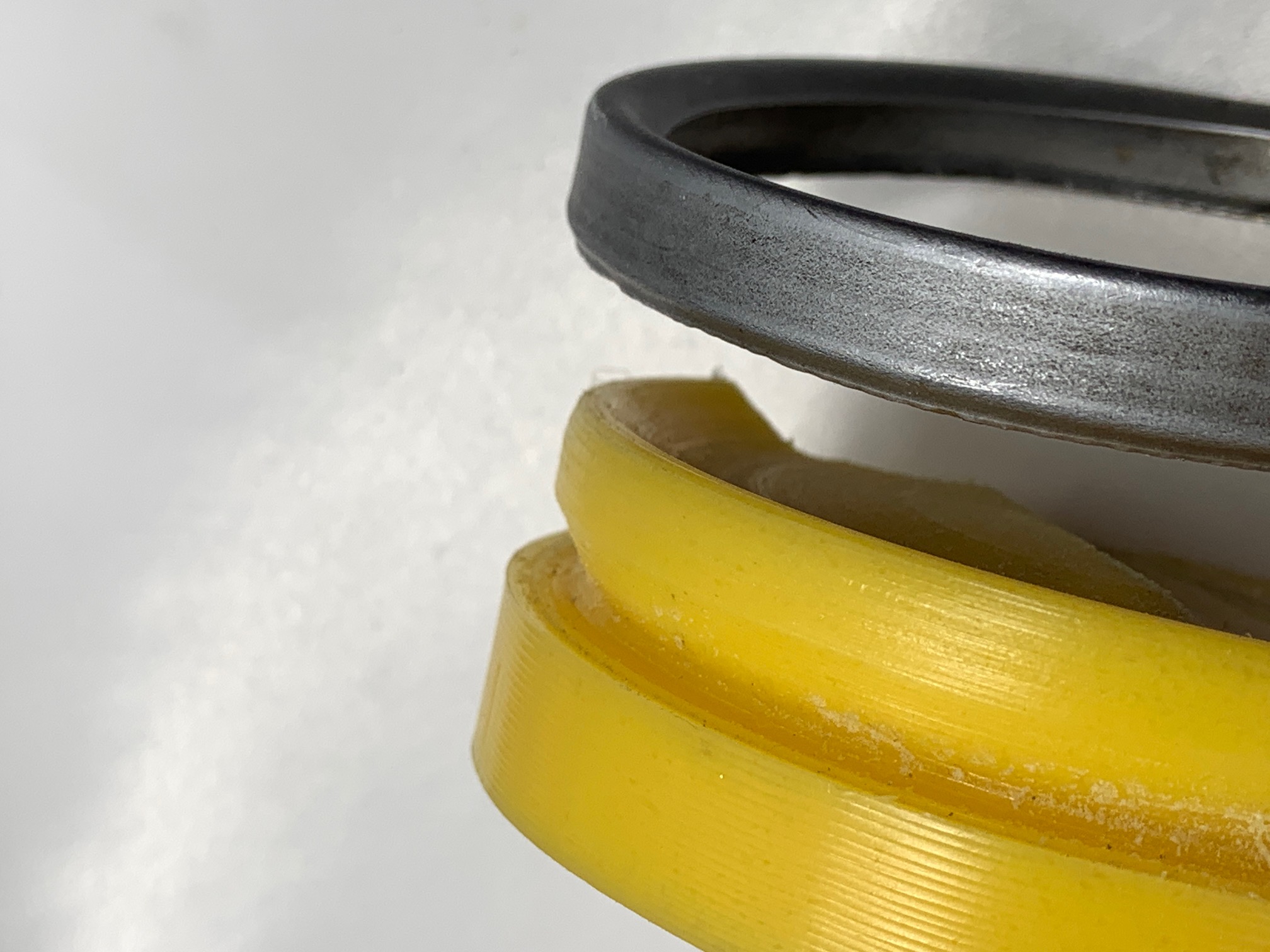
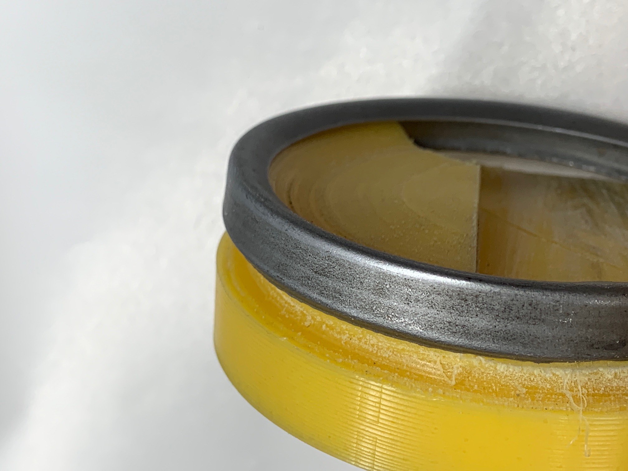
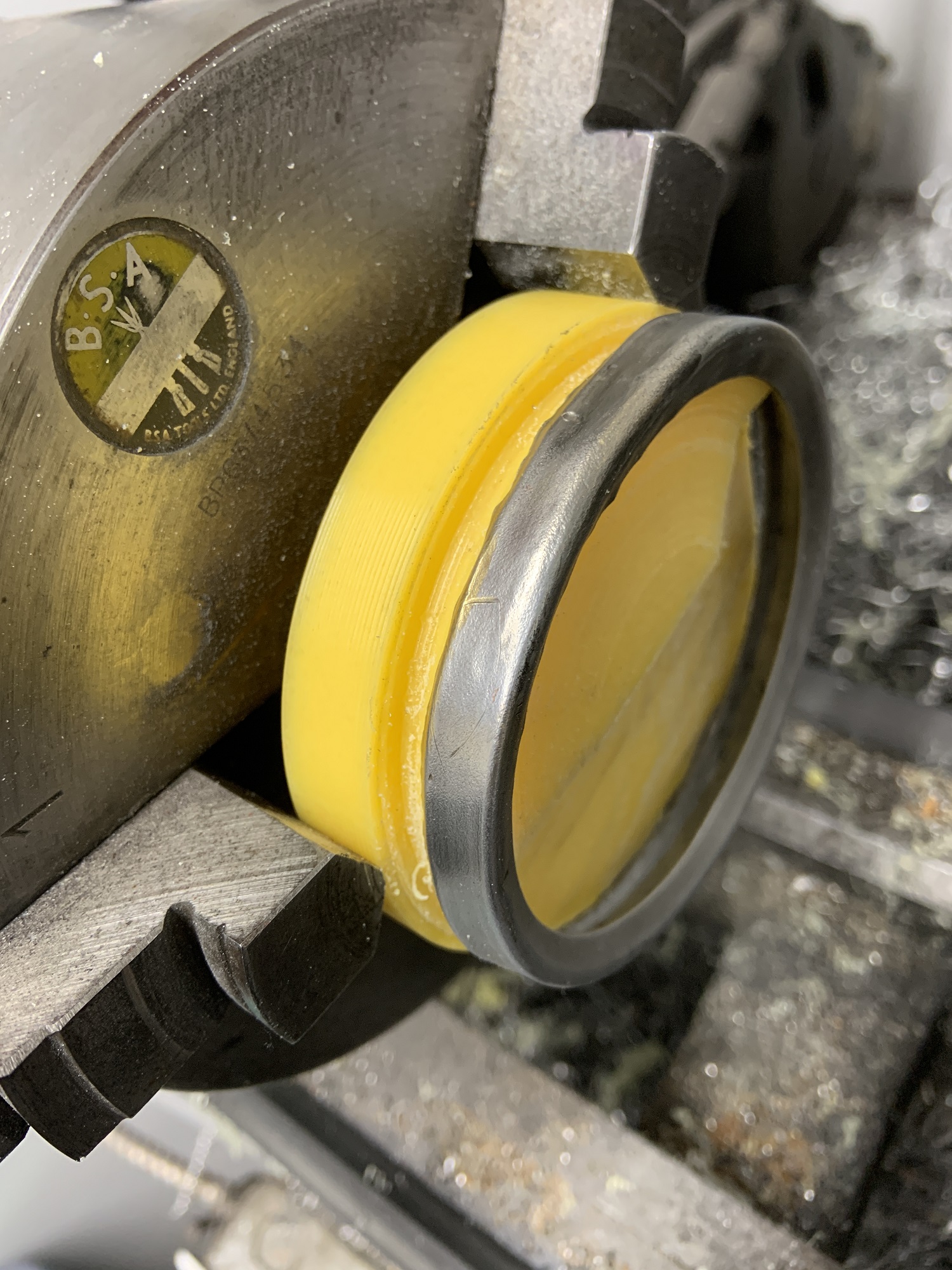
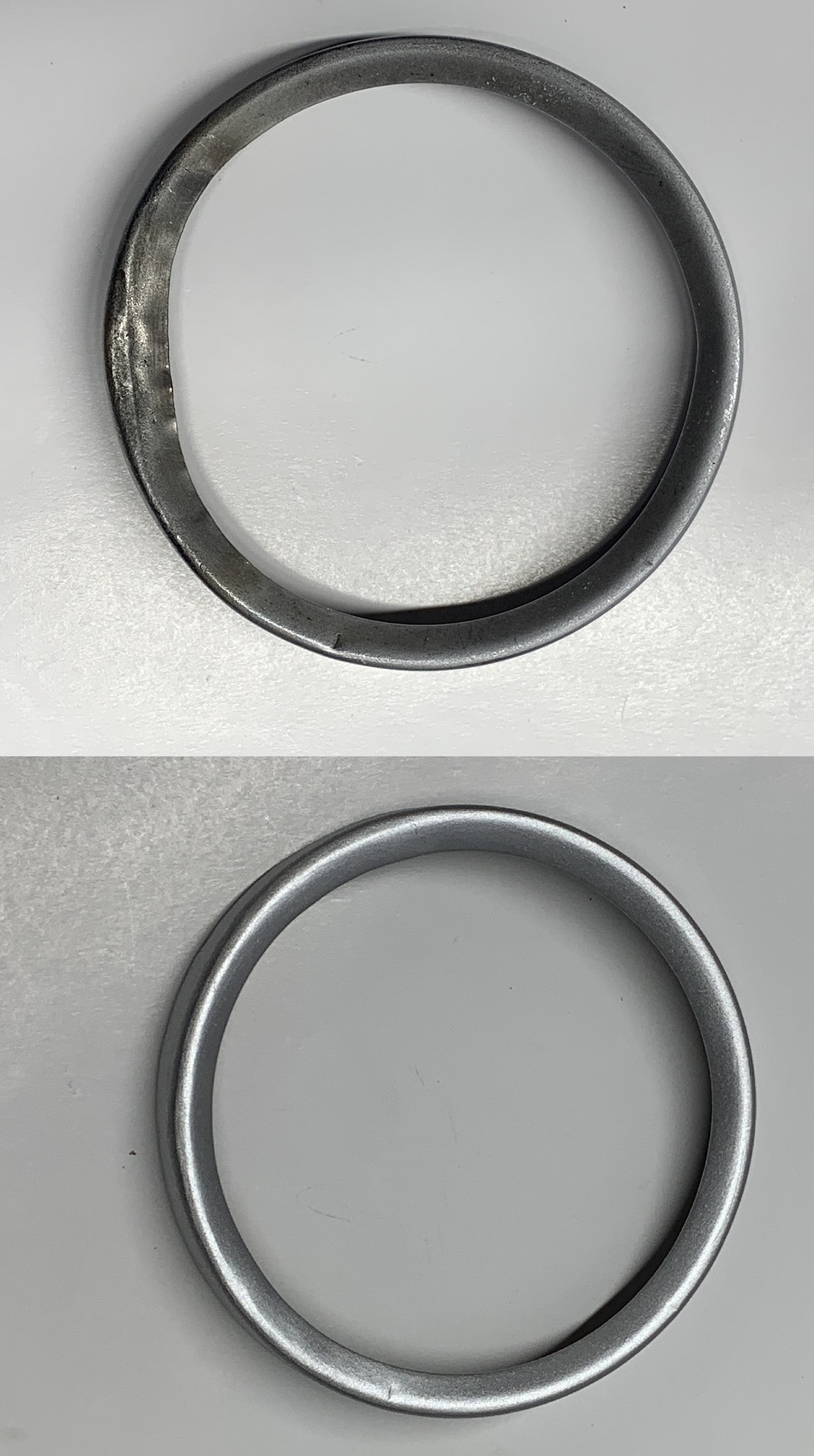
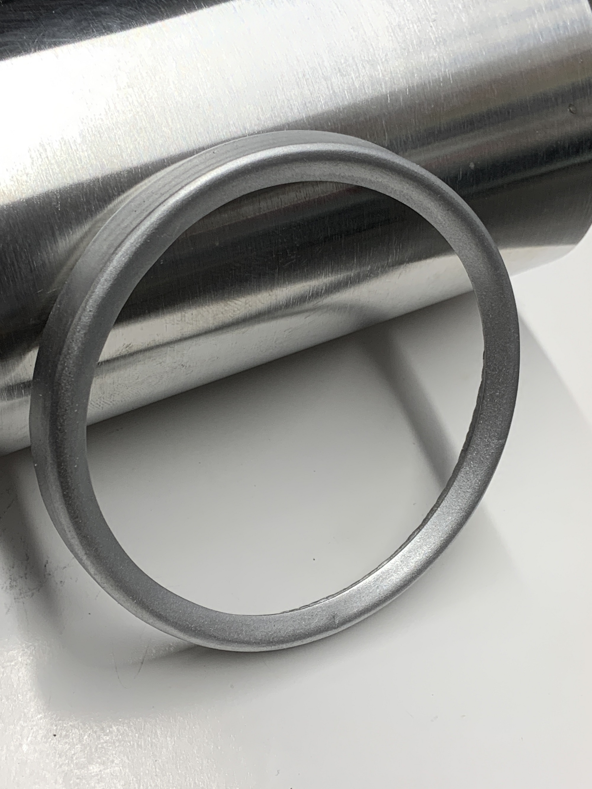
After Ian disassembled it we realized the glass is a different size. I had some new glass cut and he gave me the damaged rim to try to repair.
So in these early stages of attempting this H2r Tach repair it was still questionable as to how good this would turn out.
I got really encouraged when Ian said he found the color match for the face plate and was going to begin to do some test printing.This takes skill, knowledge and talent and Ian nailed it. I don't think I could have resolved this repair without him making this big effort. Knowing how to disassemble and recondition instruments is way out of my wheelhouse.
Looks good Jim !! You are da Man ! I was going but the sever thunder storms put me off from riding down. Glad I didn't go..Faaacking nasty rain. Would not have been a nice ride home.
Again, I have to thank you guys for all the amazing compliments, video's and photo's.
It's been a long time since I started this project and it started as more of a dream than something that I figured I could complete.
There's a few finishing touches to fix up but you can't imagine how pleased I am with the results.
I'm happy that it's off the bench and I have another one to get going on so keep watching.
Many thanks go out to: Walms for the pipes, Zambia for the Tach, Nick Kemp for the frame tube bending and Pete for the parts donations and working with me to get the other bike.